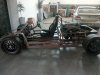
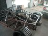
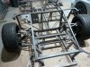
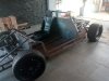
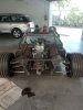
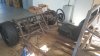
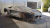
Glad to hear! I really want to watch this through its completion. As you've probably observed on other suspensions similar to this, the shock doesn't need to be in the "center" to be effective, but the shock cannot be a link used to control motion of the suspension in any axis other than the longitudinal axis of the shock itself. This is where the suspension arms/links must be designed to control motion in all three axis, which then leaves the shock to only dampen that movement, and the spring to position it (and support the weight). When you talk to your mate about this, also query him about the lower arm's lack of triangulation. The current photo, even if welded with gussets, leaves a large risk of folding up (aside from the twisting motion already noted by Jac). The uprights appear to look sturdy enough with the large gauge sheet you're using, but the arms/links will need a serious re-evaluation (in my humble opinion).
One last thing while I'm spewing out advice about your business, now that I stuck my nose in it:
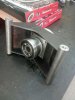
You've got steel uprights in the rear, which are of heavy gauge steel. You've got an excellent opportunity to weld the shock mounting brackets directly to the upright instead of using the ones on the lower control arm. Mounting the shock directly onto the upright does a number of beneficial things, but the most important is that it takes the corner weight off the the Heim joints (which should ideally be only used to control suspension movement). Doing this would increase the reliability (read safety) of the car tremendously by practically eliminating any shear loading on the Heim joints themselves.
Please take some time to review/study basic suspension design and forces, and utilize the many many photos on this site to validate your designs. 99% of what has been shown by builders on this site are well-vetted designs that should endure without failure for the lifetime of the car. I would also be cautious on what comes out of someone else's fabrication. If this person is not demonstrating (via the build result) a competent understanding of structural design, and the forces experienced in a chassis, then you may need to question/address that as well.
Good luck going forward.