Howard B's RCR 40

Howard,

I use Fel-Pro 1415 gaskets. Been on and off several times, no worries.

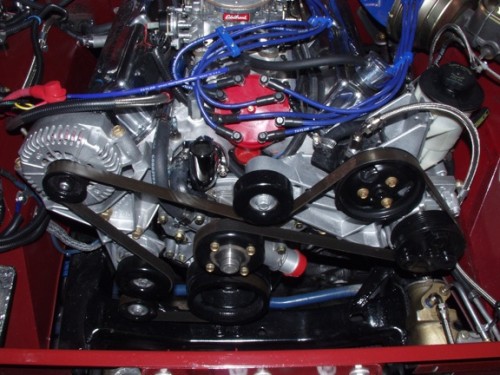
Thanks for the kind remarks about you serpentine system, I'll be sure to pass that along to Bryan. BTW - I think we only moved the engine back 1/2 inch but I'd need to check our notes. With respects to the water pump and crank pulley diameters, I think Woody is spot on. Larger water pump pulley to slow down the water flow at high rpm to allow the coolant to both absorb and disapate the heat and prevent cavitation. That's just what I found to work well over the years.

Cheers,
John
 
With respects to the water pump and crank pulley diameters, I think Woody is spot on. Larger water pump pulley to slow down the water flow at high rpm to allow the coolant to both absorb and disapate the heat and prevent cavitation. That's just what I found to work well over the years.

Cheers,
John

Well, again something learned.
So whats the reco ( rule of thump) for the relation of crank pulley dia to waterpump dia with an engine turning up to 7800 rpm and mainly be used for sure upt to 7200 RPM ( my 331 configuration)?

Thanks for your input and sorry for the tread drift

TOM
 
HI Guys
What Iv'e done in the past, and used this rule of thumb for years, is to run 70-75% drive ratio for an engine turning at 7500 rpm. I know everyone has there own ideas so I found some info in a book called POWER SECRETS by SMOKEY YUNICK He states " not to turn a standard waterpump faster than about 80% of crankshaft speed" If you can get your hands on a copy it's very good reading, even if he is referring to those funny orange motors:laugh:
 

Kevin Box

Supporter
Woody

While playing with jet boats we used to run the water pump at 50% crank speed with no issues.
Really you only have to satisfy two constarints
1 High enough speed to circulate at idle
2 Low enough speed to stop cavitation at higher speeds. Also allows water time on the hot surfaces to actually transfer heat.
You can get all theoretical on this one but if you look at what speed the pump is iniitially designed for this should be a guide as to the relative speeds you should run it in your application. Stock pump is normally expected to go to about 4000 RPM max so drive it accordingly on your engine. Just make sure it is doing the job right at idle!

Hope this helps

KB
 
Thanks for the input

BUT sorry guys something i don´tget. Look at a stock 5.0 Mustang. engine turns 6250; waterpump pulley is smaller than crank pulley , so i guess wp runs a max of around 7000 rpm. Thats much more than the 4000 Kevin talked about.

Fig_1-500x375.jpg


I know the picture is not showing a stock 5.0 but the pulleys are stock.


So either stock configuration is totaly off or i don´t check it.

TOM
 
Howard
Sorry for the drift but it is an interesting subject. Sorry but i should have stated that my rule of thumb of 70-75% is for a race engine that would see 7500rpm on a regular basis where the stock 5.0ltr or any other road car would very rearly see those numbers.
Kevin I have not run a pump down to 50% so i imagine you are right about the circulation at idle and I do agree if you spin it to fast the coolant will be circulated through the engine to quickly. when this happens the coolant doesnt remain in the engine long enough to efficiently absorb heat and carrt it away to the radiator. It is a balancing act and every engine and circumstance differs. The one thing that remains the same is the more horsepower you want the more fuel you tip into it, the more fuel the more heat you make, and the more heat the more volume of coolant you need to maintain the temp.
A stock low HP engine at road going rpm doesn't have the same requirements as a race engine so some where in the middle we will find our compriomise
 
My experience with stock water pumps and pulleys is that they are set for max cooling at idle and mid range, that's where most standard engines spend their time. After that at 6250 the pump is most like just cavitating and lost most of it's efficiency. A standard engine usually does not spend it's whole day on the rev limter but at idle in traffic when it's stinking hot with the A/C on and all the electrics loading the motor.

I would work out what the mid range speed of a standard water pump and pulley is and then size it to your modified engine revs.
 
Of course you could always go to an electric pump with a PWM that would do all of that automatically. I will shortly find out if a low flow rate will do the job. Others have the big flow of 55 gpm or so and have no trouble. It also frees up some horsepower.

Bill
 
Well it's been a while since I posted, time to get caught up.

Thanks for the attention to my pulley size, I have it on and ready to go. If it doesn't keep it cool enough I can easily swap it out.

In the mean time on with the build...

John Schriver machined my valve covers for breather holes and a screw-in oil filler cap. There are custom oil splash baffles for the inside of the breather holes. The oil filler plug seals with an "O" ring. A couple of lines and I will have them attached to the oil puke tank. See pictures attached.

Ps. Woody, where are you in Kiwi land?
 

Attachments

  • Valve cover baffle 002 W.jpg
    Valve cover baffle 002 W.jpg
    30.1 KB · Views: 342
  • Valve cover Baffle in 010 W.jpg
    Valve cover Baffle in 010 W.jpg
    26 KB · Views: 364
  • Valve cover oil plug 004 W.jpg
    Valve cover oil plug 004 W.jpg
    23.4 KB · Views: 351
  • Valve cover oil plug 013 W.jpg
    Valve cover oil plug 013 W.jpg
    32.3 KB · Views: 381
  • Valve cover eng 020 W.jpg
    Valve cover eng 020 W.jpg
    44.2 KB · Views: 490
I have the front of the car pretty much ready to go. The heater hoses pass through the front bulk head and are insulated from chafing with standard oil filler grommets purchased at the local auto parts store. The 5/8th inch hoses are a snug fit but a little liquid hand soap did the trick. (Nothing like a little lubrication to make things work.) The Isis Power Cell supply is mounted on the upper right hand side of the bulk head.
 

Attachments

  • Front Hoses  006 W.jpg
    Front Hoses 006 W.jpg
    40 KB · Views: 507
  • Hose pass thru 005 W.jpg
    Hose pass thru 005 W.jpg
    40.7 KB · Views: 430
A couple more details... the Isis master cell is mounted forward in the passenger foot-well well forward of where any feet will reach if and where the access panel can be removed and the computer can easily be read from the passenger side from outside of the car.

Another little add on is a Ford fuel strainer for the end of the fuel pick-ups which will feed my swirl pot. This was an idea from my friend Big John as opposed to my friend (little) John. :laugh:
 

Attachments

  • Computer 018 W.jpg
    Computer 018 W.jpg
    26.9 KB · Views: 434
  • Fuel strainer 015 W.jpg
    Fuel strainer 015 W.jpg
    30.4 KB · Views: 394

Dimi Terleckyj

Lifetime Supporter
Hi Howard

Just a quick thing to consider RE your filter on the pickup.

Personally I would not put a filter on the pickup in the tank for a number of reasons.

1. When the filter blocks up with all the dirty fuel from the servo's you won't know until the car starts to experience starvation.

2. To check or service the filter means you have to dismantle the pickup and your fuel sender each time.

3. All the debris gets left in the tank to build up over a period of time.

A much better way is to leave the pickup pipe open and put a good quality filter separator outside the tank before the fuel pump which will keep all the debris from entering the pump but with the added advantage of syphoning all the crap out of the tank which then remains clean and allows visual inspection of the filter bowl to check for dirt and / or water that can be easily emptied, cleaned and refitted with a minimum of tools and fuss.

Just my two cents worth but works for me.

Dimi
 
Hi Dimi,

We had that debate up front for the strainers. I agree with everything you have said and I am even considering not even using the tubes at all in the long run. I am using the Dynatek Classic fuel injection (seen in the last valve cover photo). I note from your posts you always seem to have good answers. The reason I am starting with this is the tanks are aluminum, new and clean. I am just moving the gas to the swirl pot then to a two filter high pressure pump system for the EFI. I am currently studying the use of internal fuel pumps in the main tanks to the swirl pot. They are not moving gas directly to the engine. The root problem is hanging three pumps and all their filters and fittings in the engine bay. It starts to look ugly! The two strainers and the other filters come into play before fuel hits the injectors. Thanks for joining the discussion. If you have some more ideas please let me know, I am into studying every thing.

Hi Chuck,

I got the idea from you, but I just didn't like the look of the "7IO" plug from the parts place which I had purchased after looking at your valve cover set up. The new oil plug would look just a little better with GT40 logo/emblem etched in it.

BTW, I continue to consult the Chuck and Ryan Build manual you presented me at Road America. It's a great compilation of build information. I am grateful.
 

Dimi Terleckyj

Lifetime Supporter
Thanks Howard

The main reason I said anything is that, the same as you, when I built my 40 I had brand new clean stainless tanks and the amount of debris that has accumulated in my filters from dirty petrol from servos has me amazed.

I have done 15000Km's in my 40 the last 2 years and to collect so much crap in the fuel in such a short time is incredible.

If you are going with internal fuel pumps in the tank then you have no choice but to put filters in the tank as well but it means you will have to be very thorough with your maintenance on a regular interval.

In all my cars I have found the most reliable way of handling fuel is to go from the tank straight to a filter and then to other components which means only clean fuel will run through pumps, swirlpots etc and not be allowed to contaminate or build up in these other components

Dimi
 
Last edited:
Okay Dimi I've got my thinking cap back on! The good news is no large sum of money changed hands for the strainer. Thanks for trying your best to keep me out of trouble.
 

Chuck

Supporter
Hi Dimi,


Hi Chuck,

I got the idea from you, but I just didn't like the look of the "7IO" plug from the parts place which I had purchased after looking at your valve cover set up. The new oil plug would look just a little better with GT40 logo/emblem etched in it.

BTW, I continue to consult the Chuck and Ryan Build manual you presented me at Road America. It's a great compilation of build information. I am grateful.

Howard:

I will let you in on a little secret. I am not using the "710" oil filler plug. Got a generic rubber plug that is a bit less conspicious and works just fine.

I am working on the sequel to the 'build manual' I shared with you. Revisions and updates, most significantly the transmission swap. Up to about 50 pages. It has been almost four years since we started the GT project and we are still having more fun with it than a gopher in soft dirt.
 

Randy V

Moderator-Admin
Staff member
Admin
Lifetime Supporter
Nice work Howard!

RE: Fuel strainer
It really is a dual purpose device;
1) Obviously to filter out large particles to keep them from compromising your fuel pump
2) Decreases the potential for cavitation on low fuel levels my increasing the surface area of the inlet.. (Ever wonder why oil pump pickups aren't just a tube stuck into the oil?)

I'll be using fuel strainers on my inlets, but they are much larger(Pics below)

I bought a few of these from a seller on eBay;
3/8 gas fuel tank sender side pickup line strainer,carb: eBay Motors (item 180537135344 end time Aug-02-10 18:56:47 PDT)

If you chose to not use strainers, you may want to create a couple of Duck Bills (some people call them Duck Feet). At any rate, I've made my own before and they're really quite simple to make. Picture below has all the info.
Just have enough of the Neoprene tubing so that the duck bill lays on the floor of the tank..


Duck-Bill.jpg


I hope this helps...
 

Attachments

  • Screen shot 2010-08-01 at 11.08.28 AM.jpg
    Screen shot 2010-08-01 at 11.08.28 AM.jpg
    8.4 KB · Views: 290
  • Screen shot 2010-08-01 at 11.08.49 AM.jpg
    Screen shot 2010-08-01 at 11.08.49 AM.jpg
    17.2 KB · Views: 302
Back
Top