Great find; think I'll copy that! Thanks

- Forums
- GT40 Replica Manufacturers' Corner
- RCR Forum - RCR40/SLC/917/Superlite Aero
- The SLC Clubhouse
You are using an out of date browser. It may not display this or other websites correctly.
You should upgrade or use an alternative browser.
You should upgrade or use an alternative browser.
Rumbles SLC Build
- Thread starter rumbles
- Start date
-
- Tags
- g50 gear ls3 powernation rumbles slc superlight yellow
One of the challenges of building any fiberglass car is getting the cabin water tight. There is nothing worse than having the rain pour in through all the little gaps while you are driving.
The first time I drove my completed SLC, it was on a Saturday to debut it at the Charlotte AutoFair car show. Unfortunately, it rained all day and well into that evening. I nearly drown on my drive home from all the leaks!
The weatherstripping I had already installed took care of 95% of the gaps:
The first time I drove my completed SLC, it was on a Saturday to debut it at the Charlotte AutoFair car show. Unfortunately, it rained all day and well into that evening. I nearly drown on my drive home from all the leaks!
The weatherstripping I had already installed took care of 95% of the gaps:
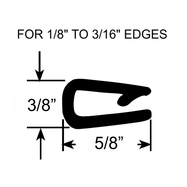
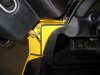
- I installed a rubber "C" shaped edging with a steel inner stiffener around the upper door opening on the body. The edging dresses up the fiberglass edge and holds the interior ceiling panel in place.
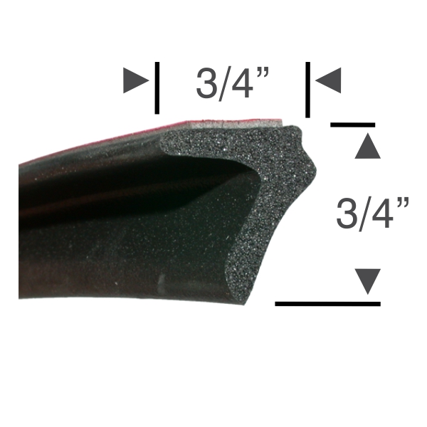
- I applied Steel Rubber Products "L" shaped 3/4" roof rail weatherstripping (PN: 83-0139-73) around the edge of the doors. This roof rail weatherstripping is pricey at $40 per 10' chunk, and you need 4 chunks. There are several twists and corners where the weatherstripping must be cut/mitered to achieve a good fit. The Steel Rubber weatherstripping glue works well to stitch all the cuts back together.
- The front tires throw water/mud up over the inner fender and it fills the "cup holder". When you accelerate, the water/mud in the cup holder sloshes backward and into the cabin. Drilling a drain in the cup holder solves the problem.
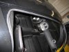
- The door weatherstripping was not quite wide enough to fill the gap to the top of the front fender, so I added some 1/2" "D" shaped weatherstripping.
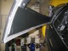
- The door weatherstripping was not quite wide enough to fill the gap to the top of the rear fender, so I added a short section of the same 1/2" "D" shaped weatherstripping.

Attachments
Thanks for sharing! This level of detail is priceless. It's a major help!
A.J.
A.J.
I had been hoping somebody would tackle this question.
Really great information here Bill. Thanks for taking the time to document the cause and effect along with comprehensive solution information.
The real world road testing in actual rainstorms instills confidence in your readers")
Did any of this effect the way the doors close or door gap/panel alignment?
Really great information here Bill. Thanks for taking the time to document the cause and effect along with comprehensive solution information.
The real world road testing in actual rainstorms instills confidence in your readers
Did any of this effect the way the doors close or door gap/panel alignment?
The body to door gap is not constant around the door, so the compressible nature of the "L" shape weatherstrip helps bridge the gap in most places. There is some tension at first from the weatherstrip in the tighter gaps, so the door will have to slammed hard the first time. Then just let it sit overnight and the Steel Rubber weatherstrip will compress and retain "some" memory. The doors now close fine with solid sounding "thud". A tight seal also quiets interior noise significantly.I had been hoping somebody would tackle this question.
Really great information here Bill. Thanks for taking the time to document the cause and effect along with comprehensive solution information.
The real world road testing in actual rainstorms instills confidence in your readers
Did any of this effect the way the doors close or door gap/panel alignment?
Bill
Great post......saves us/me hours of research and homework. Devils in the details.
:thumbsup:
Great post......saves us/me hours of research and homework. Devils in the details.
:thumbsup:
Bill thanks for the information. Can you tell me where you purchased the "C" shaped weatherstrip and the part number? The car is awesome!
Bill thanks for the information. Can you tell me where you purchased the "C" shaped weatherstrip and the part number? The car is awesome!
Gosh, I bought it long ago at (believe it or not) JC Whitney. They had the best price. Its a common molding so its available from many other suppliers like McMaster, Steel Rubber, etc.
Bill
Great post......saves us/me hours of research and homework. Devils in the details.
:thumbsup:
Thanks, speaking of details...
I have a couple areas where the "L" weatherstripping folds over when the door is closed. If I had to do it all over again, I would try pointing the "L" flap inward around the door vs mine which is the more typical outward direction.
Hey Bill,
That belongs on the wiki..
Jack, Funny you should mention that.
I was on the wiki last week trying to add some content, but couldn't seem to log on.
Could the wiki owners send me a PM on what I need to do to get write access.
Jack, Funny you should mention that.
I was on the wiki last week trying to add some content, but couldn't seem to log on.
Could the wiki owners send me a PM on what I need to do to get write access.
PM coming...
-Will
Sometimes you need to drive your car to find and fix those little annoying problems. The defroster was one of those areas that needed a bit of tweaking. The air blows just fine through the defroster vents, but the majority of the air bypasses the center portion of the windshield and defrosts just the outer corners of the windshield.
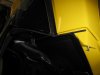
While I had the dashboard out this past winter, I added 2 vanes to each side of the defroster to direct more air to the center of the windshield. The vane installation was a bit tricky, since I had fiberglassed an air tight plenum to the underside of the dash.
FYI, The vanes were painted flat black before final installation.
Attachments
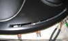
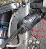
Like all rack and pinion steering units, the SLC has rubber bellows on the ends to seal out dirt as the tie rods slide in and out. However, when the rack is turned to full lock (in either direction), the rubber bellows are stretched quite tight. In fact my rubber bellows ripped with about 3K miles on the clock.
Replacing the bellows is simple, but you can easily prevent this early failure by reducing the stress on the boot. Just release the plastic clamp that holds the small end of the bellows to the tie rod. Then slide the bellows inboard along the tie rod a few inches. The tie rod diameter is larger there so the bellows fits more snugly. In fact, the fit is tight enough that the original plastic clamp is no longer needed.
Replacing the bellows is simple, but you can easily prevent this early failure by reducing the stress on the boot. Just release the plastic clamp that holds the small end of the bellows to the tie rod. Then slide the bellows inboard along the tie rod a few inches. The tie rod diameter is larger there so the bellows fits more snugly. In fact, the fit is tight enough that the original plastic clamp is no longer needed.
Attachments
Good tip . Devils in the details. :thumbsup:
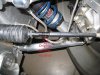
I saw this approach on another forum for building a tighty looking exhaust. It starts with a LS7 header, which makes a great foundation with its higher flow, thermal insulation, and noise insulation. You can find a used LS7 header for as little as $75.
First cut the exit flange off the LS7 header. I can tell you from experience that the combined weight of this flange and the mating flange on the down pipe is significant. This saves about 10-16lbs!

Use a cut-off wheel to split a 3"90 degree stainless steel elbow down the middle.

The down pipe starts by welding each half of the elbow directly to the LS7 header. The down pipe looks like it would flow like a hurricane and allows a much tighter bend in the close confines of the SLC. To point the exhaust rearward, just rotate the cut in the elbow 90 degrees and weld the halfs on fore and aft.
The header and elbows are stainless steel, so you will want to set up your welder for stainless steel as well (SS filler and Argon/CO2 gas).

The down pipe isn't completed in the above photo, but you can see where he's going. He will be filling in between the elbow halfs and terminating the down pipe with a ring connector to seal to the rest of the exhaust system.

First cut the exit flange off the LS7 header. I can tell you from experience that the combined weight of this flange and the mating flange on the down pipe is significant. This saves about 10-16lbs!
Use a cut-off wheel to split a 3"90 degree stainless steel elbow down the middle.
The down pipe starts by welding each half of the elbow directly to the LS7 header. The down pipe looks like it would flow like a hurricane and allows a much tighter bend in the close confines of the SLC. To point the exhaust rearward, just rotate the cut in the elbow 90 degrees and weld the halfs on fore and aft.
The header and elbows are stainless steel, so you will want to set up your welder for stainless steel as well (SS filler and Argon/CO2 gas).
The down pipe isn't completed in the above photo, but you can see where he's going. He will be filling in between the elbow halfs and terminating the down pipe with a ring connector to seal to the rest of the exhaust system.
It's a one-off home built car.
What in the name of Jackie Stewart is that LS stuffed into?
Problem: The front indicator lights only have 1 LED, yet the ISIS system has separate parking and signal wires which require a separate LED for each.
Solution: Here is a $5 solution. Go down to your local Radio Shack and buy:
- 2 560ohm Resistors (PN:271-1116)
- 4 Diodes (PN:276-1102)
Connect the circuit as shown in the attached diagram and then splice it in to the light wiring and cover with heat shrink tubing to protect it.
Job done...
Hi Bill, I'm reading through notes that I have taken and stumbled upon the thread above (thread #517 if anyone wants to go back and see the diagram and photo). It made no sense to me at the time you wrote it because I didn't have my car yet. Now it is pertinent. I spoke to Jay Harris last week about solving this problem of having the front marker light receive inputs from the turn signal and driving lights with a single positive lead. It can be done by reprogramming the Infinity Box, yet we did discuss a circuit like the one you used. My question is first of all, why the resistor? Is it to make the marker light more dim than the turn signal, so when the marker light is on, when the turn signal is activated the marker light alternates from bright to dim? That's essentially what the IB solution will be.
I'll need to do something similar for the tail lights because I fabricated my own and have a separate element for the turn signal. The standard IB system has one output that handles the turn signal and the brake lights. To complicate matters, I have added a 3rd brake light. I don't think there is any way around having to send my mastercell to IB for that one. I could add relays, but that sort of defeats the value of the IB, and I have other features I want them to program for me as well.
A.J.
Similar threads
- Replies
- 26
- Views
- 8K
- Replies
- 7
- Views
- 6K
- Replies
- 4
- Views
- 10K