Roaring Forties 105

Hi Jim,
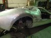
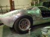
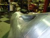
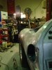
I’m blown away by the quality of your workmanship and the finished car will be a testament to your skill & dedication.
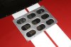
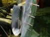
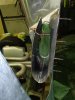
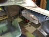
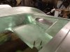
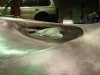
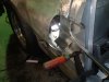
However catching up on your recent postings, I think that the proportions on your 9-hole grille need reviewing; basically the holes need to be bigger. Based on the panels I’ve recently been made, it needs to be based on two 65mm diameter holes spaced 50mm apart to get the right proportions to the rest of the panel
Keep up the excellant work
Regards,
Andy
 

Attachments

  • 9 hole rear vent.jpg
    9 hole rear vent.jpg
    162.9 KB · Views: 321
I think I can manage that.

I had nothing to go off when I made them 2-3 years ago, time for new ones I think.

Andy are they sollid rivets ,they look good.
 
Last edited:
Chris thanks but I cant buy anything that I can make, My wife keeps telling me I have a problem.

Andy are they solid rivets.
Looks good.

Jim
 
Last edited:
I was surprised when I saw this up. I almost have the rear finished but I want to get the inner panels in then I will post.
I took a few week ends off because I felt I had lost my mojo.

In the time off Dave, Ian I made the base for a sun dial for my front yard.
I made this because I needed to practice the shapes that is on the 40 and I didn't want to make scrap.
It is a shape that I keep having to make on the car.
The stand is a compound at the top and convex at the bottom and I put it through a twist at the same time just to make it look better.

Jim
 

Attachments

  • P6100044.jpg
    P6100044.jpg
    92.7 KB · Views: 499
Last edited:

Peter Delaney

GT40s Supporter
Jim, your wife might just be right !! A sundial for someone who gets up at 4am to do metal-work is a little problematical !!

Beautiful work on the sundial pedestal - looking forward to some more pics of the '40.

Kind Regards,

Peter D.
 

Randy V

Moderator-Admin
Staff member
Admin
Lifetime Supporter
I can't help but drool all over myself when I visit this thread...:bow:
 
Ok Im back.
I will put up what I have but I will have more over the next few weeks as I want to wind up the work on the rear clip.
I did one door and didn't have it in me to do another one straight away but after doing the rear clip a 2nd door will truly be a walk in the park.

Window ducts

I made a very basic buck to form the sheets on and get a shape for left and right.
I used the same timber work but dismantled it and assembled it in reverse for thew opposite side.
 

Attachments

  • P5280031.jpg
    P5280031.jpg
    130.8 KB · Views: 288
  • P5280032.jpg
    P5280032.jpg
    129.3 KB · Views: 315
  • P5280033.jpg
    P5280033.jpg
    102.7 KB · Views: 303
  • P5280029.jpg
    P5280029.jpg
    142.4 KB · Views: 314
  • P5280030.jpg
    P5280030.jpg
    151.8 KB · Views: 355
clever dick i need a couple of air scoops for my cobra
will send a photo you send back finished product for
next weekend i think that is a good swap
you make it sound and look so simple jim
chris
 
I have seen your work Chris I know you can do it.

As the inner window tray already exists the duct has to fit to it and blend to the outer pillar skin, travel along the floor then turn and travel up to the outer skin and front edge that meets the roof pillar.
The big hole you see the oxy bottles through is what has to be filled.

I made the duct in sections to achieve the shapes.
Once you have the shape you can clean it to a point but I am restricted by space so using a dolly and hammer/slapper to clean up is impossible.

So it will get some fillers to sort the last off it out.
 

Attachments

  • P5290035.jpg
    P5290035.jpg
    166.6 KB · Views: 324
  • P5290037.jpg
    P5290037.jpg
    160.2 KB · Views: 305
  • P5290036.jpg
    P5290036.jpg
    98.3 KB · Views: 284
  • P1010053.jpg
    P1010053.jpg
    141.5 KB · Views: 330
  • P1010062.jpg
    P1010062.jpg
    168.3 KB · Views: 309
Last edited:
Next I bonded the rear window tray in.
The duct exits that attach to the tray where then welded in and cleaned up as well as I could, again limited access limits you.
 

Attachments

  • P1010050.jpg
    P1010050.jpg
    164.2 KB · Views: 274
  • P1010051.jpg
    P1010051.jpg
    143.2 KB · Views: 254
  • 003.jpg
    003.jpg
    132.8 KB · Views: 259
  • 002.jpg
    002.jpg
    186.2 KB · Views: 290
  • 001.jpg
    001.jpg
    129 KB · Views: 300
Next stage was the lower ducts.
Again made in sections, welded together.
Some areas I cleaned like the leading edges on the entry but I have access issues on the welds on the inside so I will fill them.

You do what you can to keep the shapes but sometimes you have to take licence because the 40 was made with a file and make it in metal is different.

#1 is setting up the correct duct angle for the entry
#2 outer inner panel fitted and tacked, cleaned the leading edge.
#3 flanges finished off and ready for clean up.
 

Attachments

  • P5040003.jpg
    P5040003.jpg
    138.3 KB · Views: 258
  • P5040007.jpg
    P5040007.jpg
    69.2 KB · Views: 292
  • P1010056.jpg
    P1010056.jpg
    97.8 KB · Views: 286
Last edited:
Made part of the inner guard.
I made patterns to get me pretty close in fit.
It clears the exhaust and suspension.

I ran 3 wide beads to add rigidity and looks.
I put a wire edge on the lower exposed edge.
It fits well I will do the front panel then the other side, a heat shield then it is done.

This has been a s**t load of work.
I have learnt a lot from this panel, Its not perfect but I will sort some things with a little filler here and there but in general it is good.
 

Attachments

  • 011.jpg
    011.jpg
    158.2 KB · Views: 264
  • 013.jpg
    013.jpg
    162.3 KB · Views: 321
  • 014.jpg
    014.jpg
    127.3 KB · Views: 317
hello jim those inner panels will they be welded in or rivet and
bonded also how did you do the wire edge on panels ? finishes
them of nicely
chris
 
I noticed once I fitted the rear clip that when lifted on the hinges it would flex through a weld that ran down the hip to the top of the wheel arch.

My solution was to weld in an eyebrow panel, it also allowed me to change the shape and fill the guard with tyre.

Looked at a lot of arches ,lots of differences so I did my own thing.

#1 is of the metal going on
#2 is the clean up stage
 

Attachments

  • P5100011.jpg
    P5100011.jpg
    140.7 KB · Views: 333
  • P5100018.jpg
    P5100018.jpg
    164.5 KB · Views: 352
  • P5110019.jpg
    P5110019.jpg
    132 KB · Views: 317
  • P5110024.jpg
    P5110024.jpg
    160.5 KB · Views: 364
Last edited:
Just some shots

That's it for a few weeks.

Thanks Clayton, yea I like it it looks like its on roids.

Jim
 

Attachments

  • P5040010.jpg
    P5040010.jpg
    133.4 KB · Views: 296
  • P5110026.jpg
    P5110026.jpg
    99.5 KB · Views: 291
  • P5040009.jpg
    P5040009.jpg
    128.3 KB · Views: 283
  • P1010057.jpg
    P1010057.jpg
    148.4 KB · Views: 261
  • 004.jpg
    004.jpg
    151.5 KB · Views: 264
  • 009.jpg
    009.jpg
    140.6 KB · Views: 278
  • 008.jpg
    008.jpg
    194.8 KB · Views: 310
hello jim those inner panels will they be welded in or rivet and
bonded also how did you do the wire edge on panels ? finishes
them of nicely
chris

The inners will be riveted and bonded.
The wire edge I used 2.4 wire alloy, you calculate the 2.4mm then pie X dia gives the od.
You want 3/4 of that ,say 5.5-6mm, you mark the sheet.
Over fold on the line, put the wire in one end and knock the sheet over to hold it.
Move along and knock over every 50-100mm to get the wire to sit in.
All this is done with a plastic mallet even wood is fine, do all this on a wood surface as you will mark the face side,everthing you put in you hacve to get out.
Once in work the rest of the fold over, I push the wire in with a peice of sheet when knocking it over to make sure it is home.
When done you clean up with a file and make any adjustments with a panel hammer to straighten any line issues, you hold it flat on the table put the dolly where the line is not straight and tap along the edge to move the outage and blend it.

I use the beader to do the fold but it can be done using a shifter on the ege and take a few passes at it till it is up, then use a dolly in the corner to hold the shape and get the fold to come over a bit.

Chris you dont need a beader a shifter works well, I use it more than the beader on most jobs.

I can do pics of the next one if you need more info.

Jim
 
Last edited:
Back
Top