Converting RHD SLC to LHD

Kyle

Supporter
Kurt, Appreciate all the help! So I went back out shortly after my post and messed with it more. It turns out I need about another 1.5g more. I think I’m at 6 or so gallons of water. I wanted to keep the system simple so I do not have bleed lines. What I did was massage the return hose at the radiator which allowed me to force all that air out. I then open my steam vents on the engine and got some air out of there too. Once that water pump worked out the air pocket it was hovering around 190.

also as far as injectors go, I’m going to replace the 22lb stock ones for some flex fuel injectors that are 55lb. That should drop my duty cycle significantly and most definitely max out the HP potential with this setup.


The start button is ok for now. It is a proximity key. I may pony up for the key fob type that powers on when you are near the vehicle.

I plan to use power actuated doors with a simple relay, they are going to have to be powered continuously, hoped they don’t draw many amps.

As far as the screeching goes, it might have been the new rear main seal. I’m assuming until it got some proper lubricant it didn’t like being dry. It seems to have resolved itself.

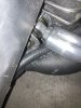
Something I’ll for sure have to do is wrap all of my ECU wiring in heat protection and get myheaders ceramic coates
 
Last edited:

Neil

Supporter
"As far as the screeching goes, it might have been the new rear main seal. I’m assuming until it got some proper lubricant it didn’t like being dry. It seems to have resolved itself."

If the screeching was from the seal being dry, its rubber sealing surface is probably damaged and may fail fairly soon.
 
Kyle. Not sure what type loom your going to use. I made a discovery that may help with heat protection. The looming that most auto stores sells have little heat protection qualities. It was by accident while in a marine supply store I found some marine grade wire loom. Discovered that It has a much higher heat protective quality than automotive grade. Needless to say, but I used marine grade exclusively in my car.
 
Dan, Kyle, what you call 'automotive grade' probably is simple TXL wiring and not really automotive grade at all for this kind of car/build.

You can google for Tefzel wire, which is the preferred motorsport high performance wiring. Very flexible, very thin, and zink coated copper strand for durability and corrosion protection. Its the only stuff used on high end motorsport wiring loom builds. Plenty of small volume suppliers to be found online, let me know if you have problems sourcing any.
 

Howard Jones

Supporter
Here's some cheap advice. Don't build a mid-engine car without a good working self bleed system. Run a 1/4 id inch hose from the top of the radiator to the expansion tank. Also, run a similar size hose from the best location on your type motor that will vent the hottest spot on both heads back to the expansion tank.

Now, most understood piece of the pie. The expansion tank must be fed from the lowest pressure point in the coolant system. This will always be the closest point in the system in distance from the face of the pump impeller. Right at the pump input coming back from the radiator is the spot. Do not compromise this point.

I have two completely different mid-engined prototypes, SBF GT40 and a SBC SLC that are done this way and they both work perfectly. Neither ever need bleeding of any sort. Just fill er up with coolant and the air all comes out by itself back to the expansion tank.
 

Attachments

  • Cooling system diagram.jpg
    Cooling system diagram.jpg
    45.5 KB · Views: 342

Kyle

Supporter
"As far as the screeching goes, it might have been the new rear main seal. I’m assuming until it got some proper lubricant it didn’t like being dry. It seems to have resolved itself."

If the screeching was from the seal being dry, its rubber sealing surface is probably damaged and may fail fairly soon.

I’m going to idle tune it when I get the time. So far the noise has went away, if it pops up again I’ll reinvestigate. I lubed the hell out of everything before I assembled because I knew it would be awhile.

Kyle. Not sure what type loom your going to use. I made a discovery that may help with heat protection. The looming that most auto stores sells have little heat protection qualities. It was by accident while in a marine supply store I found some marine grade wire loom. Discovered that It has a much higher heat protective quality than automotive grade. Needless to say, but I used marine grade exclusively in my car.
Dan, Kyle, what you call 'automotive grade' probably is simple TXL wiring and not really automotive grade at all for this kind of car/build.

You can google for Tefzel wire, which is the preferred motorsport high performance wiring. Very flexible, very thin, and zink coated copper strand for durability and corrosion protection. Its the only stuff used on high end motorsport wiring loom builds. Plenty of small volume suppliers to be found online, let me know if you have problems sourcing any.

The wiring is Holley, the only other wiring is from a place called coach controls, auto as far as I know. I’ll be wrapping the Holley harness even tho it’s meant for an engine bay. Will also ceramic coat the headers.

My cooling system is working well now, no heater core, just needed some more fluid and a little massaging of the hose. It’s all distilled water and two bottles of water wetter so nothing expensive.

Still waiting on the flywheel, just going to tidy up the wiring, finish brakes and line out the Suspension so I can get the body set in place.
 

Kyle

Supporter
Fabricated up this simple bracket to hold my DBW pedal, the cable will just barely reach it. I’ll attach some threaded ball ends when I get a chance.

A0FC3917-367F-4525-9AD5-2B8D7B09D53A.jpeg

C9FD12EF-919E-404D-A42E-976512E2B3D6.jpeg


I also got my tires mounted. I’m not sure if I have the rotors backwards, but the front rotor just barely scrapes the inner side of the wheel. I have the big rotors on front and small ones in back.
62CF19E9-E134-4CB0-8AEB-AFC12BF9B113.jpeg
045BF793-0917-4B37-8412-98367772F493.jpeg


I have the NRG quick connect steering wheel, does it press all the way into the column until the nut cant go in more?

BCA92E43-09F1-4BCC-B121-1C1C960A3360.jpeg
2EFD7C07-2ACF-4173-8270-7FA84ED0380B.jpeg


Also received my shafts from the driveshaft shop. Were anyone else’s brass colored plates a little “off”. I’m assuming once bolted to the hubs they will flatten?
348D5477-8104-490B-BFE6-136ACBA3C893.jpeg
A7AC58C2-CBE4-4049-9AE0-C1A9B3ABE0C0.jpeg
 
Last edited:
The larger diameter rotors go in the rear.

I’ve heard that some folks with the CF5V wheel option need to run spacers in the front to avoid rubbing on the caliper.
 

Kyle

Supporter
The larger diameter rotors go in the rear.

I’ve heard that some folks with the CF5V wheel option need to run spacers in the front to avoid rubbing on the caliper.
Ok so the calipers are correct then, just like a regular car. I’ll call the factory tomorrow and verify, I can’t be the only one.
 
I've read the larger rotors are for the rear and smaller ones are for the fronts. Not sure where I read this, but think it may have been on here.

My front calipers are very close to the spokes of the wheels, enough so I'm unsure if a CTS-V caliper would clear without spacers. On my car, I don't think I could run some spacers....at least not without trimming the fender lips on the inside a bit more.
 

Joel K

Supporter
That is my understanding as well.

The GM part# for the rear rotor is #92245929 and front rotor is #92245928

If you look these part numbers up on summit racing you can see the dimensions listed
Rear Diameter:14.3”
Front Diameter:13.9”
 

Kyle

Supporter
Thanks guys, I’ll sort things when I get home. Anyone have experience with the other issues? The steering adapter and driveshafts?

Also anyone have a source for the intrigue steering column cover? Found a few places but they basically come with the whole column.
 

Kyle

Supporter
So I realized in my original post I said rotors and not calipers, come to find out the calipers can only go one way, big ones in front. They do hit my wheels y maybe a mm, I have 3mm spacers that will be here Wednesday and already have extended lug nuts, hopefully that will be enough.

I finished the throttle and pedal assembly, works perfectly. Not sure how much travel the throttle pedal should have, it has maybe 1.5in of travel. Regardless, the actual DBW module is extending fully.
20E8BC4F-CEF8-4A1D-8970-4CD029742BE5.jpeg


In the last few pics you can see I was able to get everything lined up fairly well, the center console fabrication is going to be a chore seeing as how the seat is so close.

D8B35654-ADBC-49A2-A2FE-460F3ED4B514.jpeg

03C6446A-BD76-41EE-9DBC-E5B4B8DB783B.jpeg


In this last picture you can see how nice the Holley dash and stereo will fit, basically just two touchscreens and maybe a couple of buttons below the stereo.
D4E520C7-3433-48B1-B931-4525710C363B.jpeg


Does anyone have crude measurements for the front and rear suspension? Specifically MM measurements at the suspension adjustment points? I’m going to go back and look at cams blog, I thought I saw some in there. With these frames being damn near perfect, all of our starting measurements for the suspension should be fairly close assuming going with stock ride heights etc. I just want to get something close to start the alignment and then go from there. Hector? Kurt?
 

Attachments

  • 8DC0758F-4AB3-4A56-8BDA-6AE2271C0815.jpeg
    8DC0758F-4AB3-4A56-8BDA-6AE2271C0815.jpeg
    336.6 KB · Views: 204
  • 75176DEE-79BA-4D1B-89D6-EA9C3142E714.jpeg
    75176DEE-79BA-4D1B-89D6-EA9C3142E714.jpeg
    335.7 KB · Views: 208
Last edited:
Here you go. Hope pictures are helpful
 

Attachments

  • IMG_5878.jpeg
    IMG_5878.jpeg
    187.4 KB · Views: 206
  • IMG_5880.jpeg
    IMG_5880.jpeg
    187.1 KB · Views: 199
  • IMG_5881.jpeg
    IMG_5881.jpeg
    142.9 KB · Views: 195
  • IMG_5882.jpeg
    IMG_5882.jpeg
    189.3 KB · Views: 198
  • IMG_5883.jpeg
    IMG_5883.jpeg
    165 KB · Views: 197
  • IMG_5884.jpeg
    IMG_5884.jpeg
    141.1 KB · Views: 196
  • IMG_5885.jpeg
    IMG_5885.jpeg
    258.8 KB · Views: 195
  • IMG_5886.jpeg
    IMG_5886.jpeg
    170.7 KB · Views: 190

Howard Jones

Supporter
The goal is to have no tire to bodywork interference. That means a narrower rather than a wider track. Start with all four lower A-Arms as short as practical with the rod ends screwed nearly all the way in. Bottom them and screw back out a couple of turns. Now install upper A-Arms the same way.

Check Camber. If you have Neg 2-3 degrees, that's great. Now you have that much adjustability. If necessary you can screw out the lowers BUT you give up tire clearance if you do so avoid it if possible and minimize it if necessary. You can now set camber by only changing the upper A-arms rod end length. Hopefully only with the single outboard rod end that is attached to the upright.

In any final setup, the inboard rod ends on the A arms should always be the same number of turns in or out as compared to its mate on the other side. That means at the rear the two lowers are the same and the two tops are the same as compared to the other bottom or top. At the front, again the lowers are the same and the tops are the same. Do not set toe with them.

That's the end goal. Place the A-arms so that the camber can be adjusted with only the outboard rod ends on the upper A-arms. For a street car, your final setting will be neg 1/2 - 3/4 degree. Track only cars will run neg 1 to 2 1/2.

Now that you have the adjustment range accounted for, set camber to 0 on all four corners with 0 toe. Leave the car setup this way until you finish the bodywork and are SURE you have no body to tire interference.

Note: RCR told me that the washers on either side of the A-arms inboard side rodends within U mounts should be centered to get the correct caster, That's how my car is set and it seems fine to me even though I have never measured caster.

BIG ASS NOTE!!!!!! Always adjust a rod end so that when done with adjustment at LEAST 50% of the threads are screwed into the parent part (A-arm in this case). This does not include jam nut. Measure from outboard face of jam nut to end of threads = 50% of total thread length. In our case given we are working with aluminum, I have made that 60% for peace of mind. This can be a difficult rule to follow. Do it anyway.

This process can be time-consuming and a bit frustrating but if you set up the suspension this way AND THEN place bodywork at least you won't do it the other way around and find you have body to tire issues and not enough suspension adjustment to fix it AFTER you think you have finished body mounting. THAT will be frustrating!
 
Last edited:

Kyle

Supporter
Thanks Hector & Howard im going to use these as a starting point, then drop the body on and get it mostly aligned. That will allow me to get a much closer location for my tub so that I can start it’s reconstruction. AGAIN, this is only to get a closer location for my tub, it will allow me to reconstruct the parts that I cut out with some margin of wiggle room built in.

It may seem like I’m getting ahead of myself, however, I’m still missing my flywheel so I can’t go kart yet, and the exhaust is going to take me awhile so I want the approximate location of the rear clam so that I can have some margin of error for the tail pipes to exit.

One thing I’ve learned with this project is that you always need to be doing something, no matter how minuscule the task or how out of place it seems, it’s progress.

I received some 3mm front wheel spacers which give me just barely enough wheel to caliper clearance.

This weekend I hope to complete...

New nicopp brake and clutch lines.
Final routing of A/C lines (Mark sending me his crimper)
Final revision of fuel lines.
Bleed and test brakes.
Bleed and test hydraulic front lift.

The next big projects that will take some time are refiberglassing parts of my interior tub, full exhaust with valves and cats, carbon fiber skinning of front lip and side skirts.
 
Back
Top