M20 Dreaming

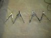
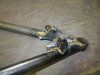
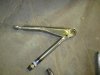
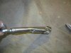
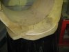
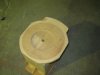
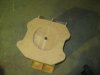
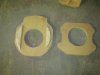
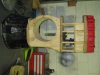
ITS totally F***ed and surprisingly I didn't have a melt down, just picked up the bits, surveyed them to see if there was any signs of life, pronounced it dead and binned it.
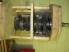
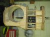
To be honest I'm sort of pleased as I had be having other Ideas but with so much time invested I decided to push ahead with the original mock up, now the decision has been made for me so watch this space. Now I have finally got my lathe powered up in my new workshop I can forge ahead with finishing the uprights, steering rack and other parts that need machining. Cheers Leon.
 
Have you not got a ' Top Shelf ' like Burts offerings to the Gods of Speed Leon? can be a sobering reminder when you start pushing the boundaries!:)
 
Hello guys, Slow progress at this point and have spent quite a few hours on the lathe. Finished the other rear upright (machining and pressing the steel bearing carrier in) and then machining the side plates that carry the diff head. This has been a lesson in making casting moulds more precise. I made my moulds with plenty of meat on them to allow for machining to the finished item, I have now spent hours making alloy swath and probably have the same amount on the floor as what's left on the Finished part, that equals $$$ on the floor so I will be machining the mould closer before casting anything else as you may remember I made this observation when I did the rear uprights, I also started the Trans axle casing design again, (starting from scratch) with a cardboard mockup. Going down a completely different path so won't elaborate until there is some real progress. I'll try to get some photos up.
Cheers Leon
 
Last edited:

Randy V

Moderator-Admin
Staff member
Admin
Lifetime Supporter
Good to read that you're still chipping away at it Leon...

Looking forward to seeing some of this work you're doing!
 

Terry Oxandale

Skinny Man
I got excited thinking this a new project, then realized that it was a much anticipated update from an old project, then got excited again :)

All kidding aside, can't wait to see some photos of the uprights.

Terry
 
Been spending some time in the workshop again. The new T/A housing is taking shape and this time there will be no exploding wood in the lathe. I have gone down a new path with this pattern and it is alot more robust unfortunitly that means more weight in the end product but I think that may not be a bad thing. Unlike the last model this one has the diff section and half the main part of the box cast as one. The back end of the casing is seperate and the gear stack will load in from the rear and the back end of the case will locate the end bearings and bolt together in much the same way the LG 500s do. I'm still working on how to do away with the 3rd shaft and QC gears, this will make the unit almost 3" shorter and save quite a bit of weight. Of course the issue is the same old one, getting that input shaft under the diff and the pinion height right for the R230, I have been thinking about adapting the the R230 R&P to a 9" carrier or just run a spool, these are the easy opions but not realy the best and it would be a shame not to have that Nissan LSD in there as they are such a good item. any thoughts. cheers Leon
 
Leon, I dont know what your long term plans are & whether you only need one TA for yourself or if you hope to perhaps market it eventually. But you might need to adjust your thought process accordingly. Using the likes of the Nissan LSD or R&P is fine for you on a one of, but if you want to appeal to the wider audience you have to use parts etc that are readily available & have options for those with different requirements. I believe there is a market for someone to build an alternative the Hewland with all the folk building replicas of Can Am stuff etc. One thing I have noted in reading about Hewlands is they did have problems, particularly in the R&P. But ignore all the advice that you need sequential shifts etc, those old Can Ams had none of that stuff..Keep it Simple
 
Last edited:
Hi JacMac, I hear what your saying. At the end of the day the main aim is to have a TA for my car but if it could be of use and worthwhile to others then it would be nice to get some reward long term for the effort. The 9" is the ideal carrier, just need a R&P that has a better pinion height. I'm thinking 10bolt??
Cheers Leon.
 
Well I have spent a good amount of time on the T/A and have a final set up nailed down. This is what will be the final component list starting with ford 9" carrier with 8.8 R&P The gear box can house a ford Toploader gear set but the first one will have the Nissan 4 speed gear set which is almost identical diamenssion's to the Toploader I have set the input shaft at 2" below the axle centre line and the pinion height is 1.5" above. The out put shaft will run Winters QC gears to the pinion shaft. I have almost finished the mock set up and now working on selecters. The length of the complete box from bell housing mating surface to rear is 25" and from Axle centre line to rear of casing 18" this is 2" shorter than a G50. Will have photo proof for you all shortly. I'm feeling really pleased with the progress and would like to see it in alloy before the new year but finance will decide that. Cheers Leon.
 
Well if I get my A into G I could provide the complete rear assembly, T/A, axles, uprights, and compete suspension trailing arms links the lot. I have also set myself a goal to have the car finished by Christmas 2015. Once I have this T/A sorted I'm going to start at the front and work back the only major part left on the Mono is the radiator pontoons. Then the Body ??? lord help me please. cheers Leon
 
Did a couple of hrs in the work shop today working out selector positions and fitting the reverse idler shaft and gears. I'm now at a crossroad, Casting the diff housing is a given but I'm now thinking for fabricating the gear case. the plan is to laser cut the end plates that hold the bearings then using tube cut to precise length and studs that will sandwich the end plates and then fill in the casing flat plate. My thinking is that the end plates and studs do all the work and the side's main purpose is to hold the oil in. That is a very simplistic view and obviously the side's as such also provide a great deal of the strength. The other option is to continue with the mould and cast the main case. anyway I have taken some photos and hope you can get a rough idea as to where I'm heading. Cheers Leon.
 

Attachments

  • IMG_2590.jpg
    IMG_2590.jpg
    141.2 KB · Views: 898
  • IMG_2591.jpg
    IMG_2591.jpg
    122.5 KB · Views: 803
  • IMG_2592.jpg
    IMG_2592.jpg
    115 KB · Views: 765
  • IMG_2593.jpg
    IMG_2593.jpg
    123.8 KB · Views: 706
  • IMG_2594.jpg
    IMG_2594.jpg
    128.7 KB · Views: 721
  • IMG_2595.jpg
    IMG_2595.jpg
    138.4 KB · Views: 277
The amount of torsional twist that will be applied to the gearbox case is highest in the lower gears, hard to visualise, but it is there & slightly compounded by the QC gears. saw a graphic example a few years ago when I stripped down a Richmond T10 from an NZV8 with a straight cut & dog box conversion, you could 'see' the taper wear on the layshaft gear teeth to the point of going thru the hardening. Those cars only had 10" wide tyres & ~450hp, imagine what it would have looked like with ~15" slicks & ~700hp:)
So I would suggest casting & include some 'ribs' preferably on the diagonal to brace the casting.
I noticed mention by someone on the ZFQ/RBT thread recently that De Lynn is intending to use a 4 point dyno to analyse the Griffin prior to production, perhaps looking for similar deflections etc in the case design. Its always going to be there & becomes more of a problem with more torque input, depends more on how it affects the operation/reliability of the transaxle in question.
 
Thanks JacMac, this is the kind of feed back I'm looking for. So you suggest not just running ribs around the case but also from top/front to bottom /rear. the tubes that the studs run through will provide the lateral ribs and I always intended to run 3 ribs around the case vertically.
 
More time in the workshop this week, I have changed the mounting plate on the front of the diff section. I have made it a separate piece so I can cast different mounting adapters on the housing, I will now make a Ford/GM style mounting plate so the T/A can be bolted straight to a stock Ford/GM bell housing. I also made the left side top front suspension arm today. Again I'm changing the front arms to better suit the tub and also to be more authentic. As I work through this project I find myself becoming more obsessed with small details and scrapping things already done because it just isn't right in my mind. when the front is done I'll put some photos up, I also need to start on the brake mounts etc. Just keep plugging away. Cheers Leon.
 
I have spent the last 2 days in my workshop and have a little more progress to report. I finished the lower and upper suspension arms for the left side and now need to machine and fit the stub axle in the left side upright. The arms now need to be blasted and painted. I have not decided whether to go HPC, 2pack or powder coating, Leaning towards 2pack as I can do that myself, another option is to Nickel Plate them. I have seen some done this way and it looks like chrome without the ill affects of chroming and cheaper any thoughts gladly excepted. I have some photos and also photos of the 2 different mounting flanges that I can cast into the diff section of the transaxle, Will do one for the ford B/housing as well. I'm now off to work for a month so no progress for a while, Cheers Leon
 

Attachments

  • IMG_2597.jpg
    IMG_2597.jpg
    118.8 KB · Views: 290
  • IMG_2598.jpg
    IMG_2598.jpg
    174 KB · Views: 287
  • IMG_2599.jpg
    IMG_2599.jpg
    148.6 KB · Views: 273
  • IMG_2600.jpg
    IMG_2600.jpg
    146.5 KB · Views: 253
  • IMG_2601.jpg
    IMG_2601.jpg
    151.8 KB · Views: 249
  • IMG_2602.jpg
    IMG_2602.jpg
    169.6 KB · Views: 247
  • IMG_2603.jpg
    IMG_2603.jpg
    114.6 KB · Views: 1,685
  • IMG_2604.jpg
    IMG_2604.jpg
    111.3 KB · Views: 1,700
  • IMG_2605.jpg
    IMG_2605.jpg
    111 KB · Views: 1,707
  • IMG_2606.jpg
    IMG_2606.jpg
    115.6 KB · Views: 1,675
Hi Leon
Ive been looking for some pics for you, and I found this site

http://www.ultimatecarpage.com/sn/329/McLaren-M20-Chevrolet.html

It says the Macleren M20-3 is part of the ROFGO collection, which is only 30 mins from where I live. I have emailed them, and asked if I can see their M20-3. If I dont get a reply, I will ring them. this is a link to their website

http://www.duncanhamilton.com/rofgo-gulf-collection-by-duncan-hamilton/

The video at the bottom shows the M20-3

Im really hopeing I will be able to get the pics you are looking for

Mick
 
Hi Mick,
Thanks for your efforts I have exhausted every site there is to get photos of the front part of the tub. The 20-3 was in the Mathews Collection but last time I looked it had gone so interesting to see where it went. The 20-2 car was at a show a few years ago and I have some good detail shots of it and not sure if you noticed (I'm thinking you did) that is the 20-1 car in some of the shots on The Ultimatecarpage.com site it is clearly different in the Roll Bar to the other 2 cars, also the dash is different and the radiator intakes are slightly wider on -1, it is the car mine will be closest to.
I wish I was in a place where I was only 30mins from the real thing, looking forward to some photos if you are lucky enough to get access. Cheers Leon
 
Back
Top