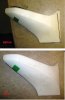
When I make right turns, my fuel vent line spills a little fuel on the payment. I routed my fuel vent hose as high as possible and over to the opposite side of the tank and then it exits thru a hole in the pan. The hose is run at an angle so any fuel in the line flows back to the tank. This is an old school setup that prevents fuel from spilling in a rollover.

I don't think a fuel vent check valve will fix the "right turn" fuel spills. In the past, I've tried a loop in the vent hose, but that holds fuel and blocks the vent like the plumbing trap under a sink.

Any suggestions?

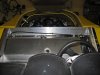
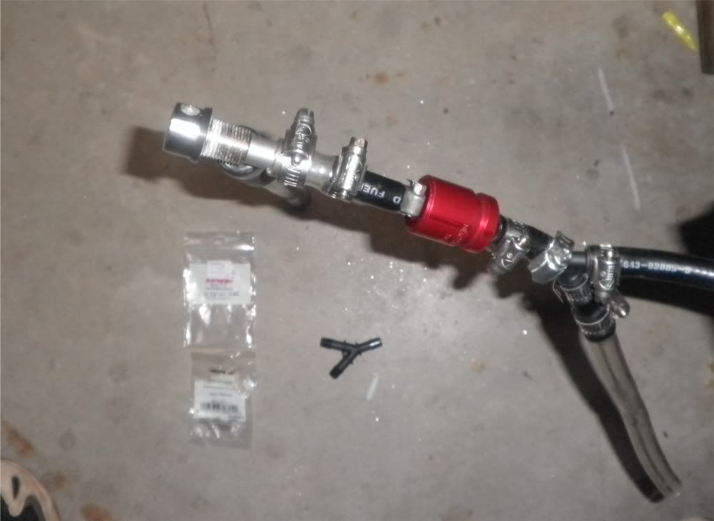
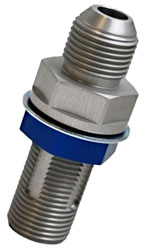
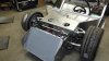
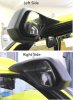
Bill - I just rerouted my vent line last night. Long story, but I also had my line looped - noted gas residue on my gas cap and weird mid-idle cruising surge. The light bulb went off - when I could barely remove my gas cap... vapor locked. My loop (plumbing trap!) was filled with fuel. I have re-routed my line as high up in the engine compartment and down. I bought a valve from Russell plumbing that I will modify but have not installed it yet. I'm going to try the new set-up first to see how much gas rides up that line. I originally had a straight NPT to AN fitting off the tank. This created a great smooth loop for the gas. I have now installed a 90* fitting to a 45* to go straight up the back engine bay panel, almost to the roof line. Test voyage later today. See the attached picture with yellow highlight for general hose route. -- Shark
 

Attachments

  • bills gas vent line.jpg
    bills gas vent line.jpg
    133.8 KB · Views: 440
Bill,

Take a look at "Killer Red tape", Polyethylene Adhesives and Glue - What are your choices.... I wanted to install my windows and light lens covers without screws too and I was considering this product.

Michael

Every time I wash my SL-C (the most water it ever sees) some of that water, and especially suds, gets under the front light covers, I have to remove the covers every time to dry the surface underneath and this is very easy with 3 external screws. I suppose if you put a decent bonding sealant on then the covers may not leak.
cheers
 
Mike and Bill,
Your old school version of a roll over valve will get you so far. I think that if you are ever in a roll over situation the lines close to the top of the car may get compromised when the body work is damaged. Unless your lines are lower than your roll cage you will probably tear up the fuel line if not a hard line and even then It could rupture. Take a look at these at Pegassus https://www.pegasusautoracing.com/group.asp?GroupID=FUELCELLVENTS
Here is a clever 2 ball arrangement.
In Line Fuel Tank Breather Valve 8mm - Car Builder Solutions
The better ones are pressure set at one or two psi. They allow the movement of air into the tank as it empties and air out as it expands under heat or while parked in the sun, but seals against flow out. They should be vented to the outside , but in an area that isn't in a crumple zone. I have mine(GT-40) set on the front of the spyder just under the back edge of the front clip.Mine came from one of the English companys, can't remember which one at the moment. Here is the complete setup for one side. I vent both front and rear to catch any air bubble with a nearly full tank.

P9060282.jpg


They will stop that right hand leak. Heaven forbid you hit the wall in a right hander.

Bill
 
Last edited:
Bill,

My vent line is routed within triangled aluminum structure of the firewall, which is one of the strongest sections of the chassis. In a catastrophic event, I would probably be crushed before fuel line:shocked:

After looking at the links in your post, I now think that a fuel vent line "Discriminator" would be a better choice than a "check valve". A discriminator has an internal float valve that closes if the line fills with fuel and a separate gravity valve that closes in a rollover. However, it may still allow small amounts of fuel to pass thru from hard cornering sloshing.

Thanks for the links!

FSITDV08.JPG
 
To see how much fuel is escaping from the fuel vent line, I taped a cup to the under carriage where the fuel vent line exits. I then filled the tank and went for a 40 minute cruise. I focused on making hard right turns, so the fuel would slosh toward the vent line bung on the left side of the tank.

When I arrived back home, I was surprised to see that the cup was bone dry!

I had assumed fuel was escaping the vent because I could smell it. In hind sight, I think the smell was coming from a very slow leak at the fuel supply line at the bottom of the tank. Fuel was weeping thru the treaded NPT fitting so I sealed it with Loctite 565.

I guess I really don't need the check valve after all.
 
I had assumed fuel was escaping the vent because I could smell it.

Bill,
If your vent line is venting the tanks into the atmosphere, without being scrubbed by a charcoal canister, that's where part or all of you gas smell is coming from.

It's basically the same as leaving a gas container open in the garage.
 
Shark,

Good point. I think I'll buy her a romantic little gift, like the Drill Press I know she has been secretly wishing for.

You just saved yourself $80-$130.00. Time to go out and buy the Miss's a nice meal for putting up with all this car stuff :chug:.
 
I still feel you need the the rollover valves and even if you re going to stick with the loops, the ends of the vent line(s) need to be outside of the body work. I say that in that my front cowling(GT-40) is closed and sealed from the interior of the car. So I mounted the vents alongside the gas fillers. I used marine vent heads that have a fine mesh inside the holes. Have no smells of gas, even when the side windows are removed.

Bill
 
To improve cooling, I've been trying to get a better idea of how the air is flowing in the engine compartment at cruising speed. So I taped a bunch of paper strips around the driver's side of the compartment and mounted a camera on the rear clam pointing down to capture a top view. I did a number of runs, but these 2 videos were the best.
Notes:
  • In rear inner fenders are installed, without the louvers cut out.
  • The side vents are cut out a bit larger.
  • The videos start at 40MPH and then accelerate to 50MPH.

What does all that paper flapping mean?
  • There is a significant amount of air coming in the side vents.
  • There is a significant amount of air coming up from underneath the floor pan and is causing an eddie current to swirl backwards.
  • There is quite a bit of turbulence.
  • The air is flowing inboard around the wheel wells

Do you see anything else?
 
Last edited:
To improve cooling, I've been trying to get a better idea of how the air is flowing in the engine compartment at cruising speed.

Bill, are you having the engine temps run away while idling or in stop and go traffic. Or, is this an issue all the time. I found that an upgrade to the radiator cooling fans solved my idling/slow traffic driving issue. I'm now using a pair of Maradyne straight bladed fans - they move a lot more air than the original curved blade lower CFM fans. They are louder and draw more current but work better and will hold the temps to about 209* while sitting still.

Just a thought - Shark
 

PeteB

GT40s Supporter
Bill,

Looking at your videos, it looks like a lot more air is going over the radiator than through it.
 
Hey Bill just a quick note to thank you for the build thread, really well done. Love the super clean work and the info on products with their links, this will really help me when i order my car and start the build process. Good luck with the rest and let me know if you get up to Seattle; i'll buy you and the Mrs a beer or two...
 
Here is my set up, backwards compared to everyone else's, Howe racing radiator 175.00 2 2800 cfm fans 200.00 sitting still or in traffic, or down the road, water never goes above 165
 

Attachments

  • DSCF0514.jpg
    DSCF0514.jpg
    179.3 KB · Views: 223
Thanks David,

Just to let you know, I'm in the process of compiling all my posts in this thread into a "SLC Build Log". I'm cleaning up the content so it's easier to follow and will then format it into a printable PDF document. Let me know if you are interested in an early copy.
Hey Bill just a quick note to thank you for the build thread, really well done. Love the super clean work and the info on products with their links, this will really help me when i order my car and start the build process. Good luck with the rest and let me know if you get up to Seattle; i'll buy you and the Mrs a beer or two...
 
I put the final touches on my hippo mirrors. Like most cars, the passenger mirror needs to angled more to get a good view down the right side. That makes the outside edge of the mirror stick out from the resin housing. I see where some builders extended the resin housing to cover he mirror edge, but I wanted to keep the resin housing's original slender profile.

Now the outer edge of the passenger mirror sticks out no further than the driver's side, but in the process I modified nearly every part of the mirror.

Angle the resin housing mount:
  • I started by cutting the passenger resin housing where it mounts to the door. This puts more angle into the entire resin housing. The solid cast resin is easy to cut with a hack saw. Then I used a file/rasp to shape it and sandpaper for the final surface. The driver and passenger mirrors are far enough apart so the difference is not noticeable.
  • The metal screw inserts are a real bugger, because the thin Allen head end tends break apart when installed. Drill the holes larger than barrel and lubricate the insert with liquid soap before driving it in.

Set the mirror deeper into the resin housing:
  • I used a Dremal tool to grind away the inner wall of the resin housing (nearest the door) so it more closely mimics the shape of the mirror's inboard edge. This allows the mirror glass to be positioned further inboard within the resin housing.
  • I used the Dremal tool again to dig out the forward facing inner wall of the resin housing where the mirror swivel mechanism is mounted. This positions the mirror glass further forward into the resin housing.
  • I used the round grinding bit in a drill to deepen the swivel ball socket in the resin mounting plate for the mirror. Since the socket was now deeper, I also cut down the flange around the socket of the resin mounting plate so the metal clamping plate would hold the ball securely. This positions the mirror glass further forward into the resin housing.
  • I shorten the mounting bolt of the swivel ball, by cutting the shoulder down. This positions the mirror glass further forward into the resin housing.
 

Attachments

  • Pass mirror.jpg
    Pass mirror.jpg
    62.3 KB · Views: 268
  • IMG_4394.jpg
    IMG_4394.jpg
    74.1 KB · Views: 262
  • Mirror Housing cuttings.jpg
    Mirror Housing cuttings.jpg
    427.8 KB · Views: 267
  • Mirror swivel.jpg
    Mirror swivel.jpg
    91.6 KB · Views: 271
  • Mirror swivel 2.jpg
    Mirror swivel 2.jpg
    238.2 KB · Views: 275
  • hippo Mirrors.jpg
    hippo Mirrors.jpg
    74.9 KB · Views: 367
Back
Top