Bill,
First let me say I know nothing about the ISIS system or how it works. But I take exception to what you said about the ignition switch and the push button start. I like the key lock feature. It adds one more layer of security. You can never have enough. I don't think anyone trying to steal my car without a tow truck woud ever get it started even if they had the key. It takes 4 seperate functions to get it to crank.
First, in your everyday driver, when is the last time you turned the switch to acessory to listen to the radio????
Second, with a push button start all you have is a connection to the starter. I routinely use my start button(key switch in off position) to spin the engine to get and check the oil pressure when I haven't started the car for some time. I can get my oil pressure up to 40-50 lbs. This way I don't have to pull the plugs to do it.
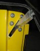
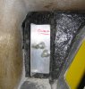
Third, You can have both an ignition key and a start button. At least I do.The start button is wired to the coil side of the relay. The relay is hot all the time. No battery drain as it doesn't do anything til the coil is closed(grounded). And I still have the acc. position available if I need it. I don't because I don't have a radio. The ignition switch when in the run position only activates the elctronics and everything else just like it is supposed to. The start position for the switch is not wired. My start key came with the wiring kit and I put it in before I decided to go with the push button. Changing that wiring around was very simple.
My start swtch is from a Honda S2000. The wiring diagram is from the web.
If you want to use remotes for locking, and unlocking wire them seperately from the ISIS system.
I understand your system is more complicated than mine. I'll leave the differences in wiring(ISIS) up to you to figure out!! I hope this gives you some things to think about.
Bill

") :thumbsup:
:thumbsup: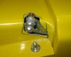


 epper: