
- Forums
- GT40 Replica Manufacturers' Corner
- RCR Forum - RCR40/SLC/917/Superlite Aero
- The SLC Clubhouse
You are using an out of date browser. It may not display this or other websites correctly.
You should upgrade or use an alternative browser.
You should upgrade or use an alternative browser.
Rumbles SLC Build
- Thread starter rumbles
- Start date
-
- Tags
- g50 gear ls3 powernation rumbles slc superlight yellow
Ken Roberts
Supporter
Bill do you have a backup plan if your single rear mounted radiator doesn't provide adequate cooling?
Ken,
The fall back plan is to go back to the standard SLC radiator.
I located the electrical components so I could run the coolant line under them. The battery would be moved up front.
I'm getting very close to a road test, so I'll know if the side radiator setup will work.
The fall back plan is to go back to the standard SLC radiator.
I located the electrical components so I could run the coolant line under them. The battery would be moved up front.
I'm getting very close to a road test, so I'll know if the side radiator setup will work.
- The car is ready to go except for 1 shifter cable. Jim at CableShift tells me I should have it next week.
- I had the NC DMV Inspector here on Thursday and passed my VIN inspection. I've also gotten my registration paperwork thru the NC DMV approval process and just need to go to the local DMV office on Monday to pickup my licence plate.
Wow!!! That's pretty dang impressive Bill. :cool2:
A while back I bought a 1990-1997 Miata lock set, so I only have to carry 1 key for both the door locks and ignition. As I looked closer, I realized that the Miata outside door handles depend upon the bearclaw to lock the door.
I modified the Miata outside door so it now locks. Its a simple change that involves fabricating a lever, adding a spring and drilling a few holes.
Checkout this YouTube video: Modifying the 1990-1997 Miata outside door handle so it will lock
I modified the Miata outside door so it now locks. Its a simple change that involves fabricating a lever, adding a spring and drilling a few holes.
Checkout this YouTube video: Modifying the 1990-1997 Miata outside door handle so it will lock
Attachments
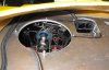
I cut a whole in the aluminum foot well for the wiper motor, but its not big enough, if you add the recommended 1/2" spacer to the arm shaft.
I used a black marker to show the enlarged hole that would include the round access porthole. That's a big hole!
Will a hole that large weaken the aluminum chassis?
I used a black marker to show the enlarged hole that would include the round access porthole. That's a big hole!
Will a hole that large weaken the aluminum chassis?
Attachments
Which motor are you using that required a hole cut in the footbox?
If the wiper shaft hole in the spyder section is moved upward by one-inch, and a little more centered, you may be able to avoid cutting the top of the footbox. Or make a very minimal cut.
There were two part numbers for those AFI Marine wiper motors. One with a long shaft and another with a shorter shaft. I assume that you have the long one. I purchased mine aftermarket (short shaft). I don't know what RCR is supplying at the moment.
There were two part numbers for those AFI Marine wiper motors. One with a long shaft and another with a shorter shaft. I assume that you have the long one. I purchased mine aftermarket (short shaft). I don't know what RCR is supplying at the moment.
I cut a whole in the aluminum foot well for the wiper motor, but its not big enough, if you add the recommended 1/2" spacer to the arm shaft.
I used a black marker to show the enlarged hole that would include the round access porthole. That's a big hole!
Will a hole that large weaken the aluminum chassis?
Bill, it should not weaken anything significantly enough to worry about.
A few builders have cut 8"x12" holes for the non-standard Manex air conditioner evap unit without reported issues. The primary load bearing structure in that area is provided by the cross beam under the dash.
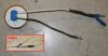
I bleed my brakes today.
There are several methods for bleeding the brakes. Some do it the old fashioned way by pumping the pedal, some use a vacuum pump on each bleed valve and some push the fluid by applying pressure to the master cylinder reservoir.
I have another method called the "Margarita Method". The process starts by inviting your significant other into the garage. After complimenting her on her garb, comfortably sit her in the driver's seat and hand her a Margarita. Then bark out the commands "Push the pedal in - Let the pedal out - Drink", "Push the pedal in - Let the pedal out - Drink", "Push the pedal in - Let the pedal out - Drink"...
I get very reliable results with Margarita Method. I ended up with a rock hard brake pedal and very pliable spouse.epper:
Lol:thumbsup:
I installed my Hippo mirrors.
It was pretty straight forward. The only modification was to the passenger mirror pod. Like most cars, the passenger mirror needs to angled more to get a good view down the right side. That makes the outside edge of the mirror stick out from the pod, so I made an angled cut the passenger hippo mirror to accommodate.
The driver and passenger mirrors are far enough apart so the difference is not noticeable.
Attachments
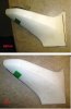
They are solid cast resin, so they cut and shape easily. I used a hack saw to cut it, a file/rasp to shape it and then sandpaper for the final touches.
The metal screw inserts are the real bugger, because the thin Allen head end tends break apart when installed. Drill the holes larger than barrel and lubricate the insert with liquid soap before driving it in.
The metal screw inserts are the real bugger, because the thin Allen head end tends break apart when installed. Drill the holes larger than barrel and lubricate the insert with liquid soap before driving it in.
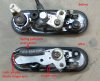
Problem: The front indicator lights only have 1 LED, yet the ISIS system has separate parking and signal wires which require a separate LED for each.
Solution: Here is a $5 solution. Go down to your local Radio Shack and buy:
Connect the circuit as shown in the attached diagram and then splice it in to the light wiring and cover with heat shrink tubing to protect it.
Job done...
Solution: Here is a $5 solution. Go down to your local Radio Shack and buy:
- 2 560ohm Resistors (PN:271-1116)
- 4 Diodes (PN:276-1102)
Connect the circuit as shown in the attached diagram and then splice it in to the light wiring and cover with heat shrink tubing to protect it.
Job done...
Attachments
My car is using these:
48 LED Super Light Red replacement light
They're pretty bright and no issues - good alternative for us electrically challenged peeps.
48 LED Super Light Red replacement light
They're pretty bright and no issues - good alternative for us electrically challenged peeps.
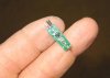
Speaking of electrical idiosyncrasies, I went round and round trying to get my Hurricane HVAC unit to work with the ISIS system. The "ahhh-haaa" moment came when I found this tiny circuit board hidden inside heat shrink tubing, midway up into the electrical harness.
The ISIS system only understands switched ground inputs, but some inputs are 12V (like from the Vintage Air HVAC). This tiny transistor circuit board converts a 12v signal to a ground signal, so ISIS can understand it.
The connections are:
Please, no criminal background checks on the fingerprints:vanish:
The ISIS system only understands switched ground inputs, but some inputs are 12V (like from the Vintage Air HVAC). This tiny transistor circuit board converts a 12v signal to a ground signal, so ISIS can understand it.
The connections are:
- The upper left wire goes to ground
- The lower left wire goes to the 12v switched input
- The right wire is the switched ground output to ISIS
Please, no criminal background checks on the fingerprints:vanish:
Attachments
Last edited:
Similar threads
- Replies
- 26
- Views
- 8K
- Replies
- 7
- Views
- 6K
- Replies
- 4
- Views
- 10K