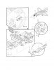
I found a schematic of the rudder pedal assembly I was talking about above. It's definitely too bulky for your project, but gives you an idea of how a similar system works. Don't mind all the boxes and wires, they're just potentiometers and sensors for the pedals. Sure wish I had a CAD program, and was competent with it. I would love to design a low profile adjustable pedal system.
But like I mentioned before, there is a lever that you pull (between your legs) that releases the assembly from the lock, and is automatically pushed to the forward-most position with a piston. In your case, if there are only two drivers, I would design the system to have their preferred position as the maximum travel for the assembly. That way they can hop in, unlock the assembly and either let it travel all the way forward for the shorter driver, or be pushed all the way to the other limit with the taller driver. You could also make those limits adjustable that way you don't have to find the same sized drivers all the time. haha
Anywho, I hope this helps out in some way.

") I don't know.
I don't know.