Looks great Bill, I told you this would get a lot of conversation. I was worried about you when you fell off the grid for a month but as seen in the photos you had a great time in Southeast Asia.
I am looking forward to coming back down and seeing your progress.
Guy
 
I further modified the Fran-kin G50 bracket and cable coupler to fit within the SLC body’s tail section. I even put a coat of black paint on it:2thumbsup:
  • I shortened the right/left cable portion of the bracket by ¾”, so it doesn’t hit the tail section.
  • I shortened the cable coupler to ¾” wide, so it doesn’t hit the tail section.
  • I welded a nut on to where the shift rod attachment bolt goes. Its difficult to drill and tap a hole in the hardened steel of the shift rod. Using a steering coupler “D” shaft approach is much easier. Just grind a flat spot on the side of the rod, weld a nut on to the cable coupler, and run a bolt/lock nut against the flat spot.
Note: The 3rd PIC shows the cable coupler when it was 1" wide, before I cut it down to 3/4".
 

Attachments

  • G50 prototype with modified bracket V2 3.jpg
    G50 prototype with modified bracket V2 3.jpg
    159.7 KB · Views: 448
  • G50 prototype with modified bracket V2 1.jpg
    G50 prototype with modified bracket V2 1.jpg
    118.8 KB · Views: 462
  • G50 prototype with modified bracket V2 2.jpg
    G50 prototype with modified bracket V2 2.jpg
    90.5 KB · Views: 419
Engine lost its Brains

I crossed a threshold this week. After troubleshooting through several layers of problems, I finally got my motor running properly.

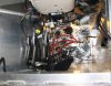
I first cranked it back in early March. It fired up on the first attempt, but then went into a very low rough idle mode and the throttle body would not respond to the e-accelerator pedal. After checking all the connectors, I read the OBDII codes using the Torque app on my cell phone with a Bluetooth OBDII reader. There was a list of codes as long as your arm and many of them were not even Chevrolet codes. Current Performance built my LS3 harness and flashed my ECM, so I called Jarad for help. Jarad suspected that something might be wrong with the program in my ECM, so I sent my ECM back to Current Performance. Jarad checked the ECM program to ensure all was OK. He found no problem and returned the unchanged ECM in April.

Needless to say, I had the same problems when I reinstalled the ECM. I suspected the Torque app I used to read the OBDII codes, so I bought a dedicated OBDII tester. Sure enough, the codes were all different. Now I was down to just half a dozen codes that pointed to the both the throttle body and the e-accelerator pedal. I already figured that, but at least the codes made sense now.

I suspected the e-accelerator pedal, so I checked to ensure the wiring was correct and then ordered a new one. I installed the new part and the OBDII codes related to the e-accelerator pedal went away. However, it still went into a very low rough idle mode and the throttle body would not respond to the e-accelerator pedal.

The diagnostic procedures for the remaining ODBII codes pointed more toward a harness problem than a bad throttle body, so I asked Jarad for a pin-out diagram.

There it was! The Throttle Position Sensor (TPS) was mis-wired in the ECM connector to pin 36 instead of pin 35. Now all codes are gone and the motor runs like a champ!
:pepper:
 
Last edited:
Yes, the mis-wire in the ECM connector was a quality problem in the harness I bought from Current Performance. I can see how you could insert a little pin in slot 36 vs 35. However, that tells me that they don't test their harnesses before shipment.

That wasn't my first experience with an electrical harness problem in this SLC build. In the ISIS system, the Push Start circuit didn't work because a wire in the front Power Cell connector was not stripped before it was crimped into the pin :shocked: ISIS Tech support helped me quickly resolve the problem. They told me that it was a known problem that they are seeing on numerous harnesses, so ya'll be on the lookout for it.

Ooo, that would suck :(
 
I mounted my e-brake calipers. Once you figure out where to locate the bracket on the spindle carrier, it just a lot of drilling, tapping and then mountain of aluminum filings to cleanup.

The bracket is located approximately flush with the side of the spindle carrier, and then toward the top of the vertical milled face. I've seen others locate it as high as it will go, but you can get a significantly larger brake pad contact patch by moving it down about 0.4"-0.5". If you move it too far down, the caliper housing rubs the disk.

Question: There were 2 mystery brackets in my e-brake kit. Does anyone know what these brackets are for?
 

Attachments

  • IMG_3232.jpg
    IMG_3232.jpg
    106.8 KB · Views: 556
  • IMG_3177.jpg
    IMG_3177.jpg
    137 KB · Views: 488
I'm told that the brackets are for mounting the e-brake handle. I don't have them, so they must be relatively new.
 
Got my AC compressor installed today.

The bottom bracket fits well and the belt alignment looks good. On the compressor, you need to push the press fitting in all the way for it to fit the bottom bracket spacing. Compressor installation was a bit difficult with the long bolt in the kit, so I replaced it with 2 shorter bolts.

The top bracket fits the front compressor mount, but requires some fine tuning. The bracket inhibits the upward swing of the compressor, so you can't get enough slack to climb the belt onto the pulley. I ground down the areas that were in the way, and that made all the difference.

The turnbuckle adjuster on the top bracket is not in alignment with rear mount of the compressor. I bent the ends and added a 1/2" threaded spacer to ensure the rear of the compressor is supported.

The belt that came with the kit was a little too long (Gates 040370), so I replaced it with a shorter Gates 040360.

All in all, it looks like a solid mount.

Today was the warmest day this year here in Charlotte. The thought of ice cold air coming out of my AC vents kept me going.:sweatdrop:
 

Attachments

  • IMG_3245.jpg
    IMG_3245.jpg
    165.8 KB · Views: 428
  • IMG_3251.jpg
    IMG_3251.jpg
    102.2 KB · Views: 428
  • IMG_3252.jpg
    IMG_3252.jpg
    185.3 KB · Views: 414
  • IMG_3248.jpg
    IMG_3248.jpg
    120.8 KB · Views: 404
  • IMG_3253.jpg
    IMG_3253.jpg
    222.1 KB · Views: 460
Ben sent me a PIC of his AC bracket. His is the mirror image of mine, and I think it's the correct side of the mirror. It allows space to put the turnbuckle on the inboard side of the bracket and aligns better with the compressor mount, so you don't have to bend it.
 

Attachments

  • AC compressor mount mirror.jpg
    AC compressor mount mirror.jpg
    208 KB · Views: 493
Bill,

Bens is in the correct orientation.....no bend and no clearancing should be required....

Brandon just checked the whole box of brackets and they are all correct...you got a lame duck...new one on its way to you today....sorry about that
 
Engine harness, ISIS, compressor bracket.......Your ability to effortlessly work through the issues is outstanding.
 
I finished installing my pedal assembly today.

I used the e-accelerator pedal from a 2010 Corvette and cutoff the excess pedal lever. I adapted the Tilton bracket that is for the GM Performance accelerator sensor and beefed it up to withstand the additional spring force of the Corvette pedal. I also removed the spring on the Tilton accelerator pedal. I worked out the leverage so its about the same pedal pressure as stock. I found a clevis assy in a local NASCAR salvage yard. Yup, here in the Mooresville NC (Race City USA) we have so many NASCAR teams, that we actually have NASCAR salvage yards.

I cut/adjusted the clutch and brake master cylinders so the pedal position would be in line with the accelerator. Then I bench bled the master cylinders before installation.

I tried a number of different positions for the pedals assy and settled on pushing them way into the foot box to about 1" from the end. I'm 5' 11" and my seat is all the way back, but that pedal position seemed about right for me. I simply drilled holes in the floor and solid mounted them.

I kept the full length of the brake lines and reservoir lines to allow lots of room to pull the pedal assy out for maintenance.

The modifications I made to the steering column really paid off. I moved up both the telescoping/tilt motors and cutoff the forward most portion of the column structure. Now there's lots of room to toss my tootsies to and fro!
 

Attachments

  • IMG_3223.jpg
    IMG_3223.jpg
    120.3 KB · Views: 507
  • IMG_3259.jpg
    IMG_3259.jpg
    211 KB · Views: 562
  • IMG_3260.jpg
    IMG_3260.jpg
    218.5 KB · Views: 618
Last edited:
Engine harness, ISIS, compressor bracket.......Your ability to effortlessly work through the issues is outstanding.


Vidal, I absolutely agree!


Following Bill's built is like watching a reality show of:
“If Can Go Wrong, It Most Likely Will.....Bill”.
My hat is off to Bill for working his way through these problems.


I just hope that I don't have to deal with these Gremlins on my build!
Jim
 
Vidal & Jimer, Thanks for staying tuned to the reality show:laugh:

There was a hidden episode from way back on 2/1/13 of the reality show series. When my SLC was delivered, the body had suffered significant damage during transit. The nose had fallen off its shipping supports, so it was resting on the upright aluminum structure that holds the radiator. After riding in the pendulum end of a goose-neck trailer for 600 miles of mid-west pothole roads, those aluminum supports dug holes at the way thru the fiberglass! That's right, I had 2 holes in my front clam when it arrived...Yuk!

I gave Fran a call to see if there was anything that could be done. Fran quickly called Tony at Performance Fiberglass (Canadian manufacturer of the SLC body) and arranged for a repair. Fortunately, Tony happened to be passing thru NC and agreed to pickup my nose.

Just moments ago, Tony knocked on my front door and delivered the repaired front clam. It looks great!

Many thanks to Fran and Tony!
 

Attachments

  • Front clam damage - Hole on Pass side 3.jpg
    Front clam damage - Hole on Pass side 3.jpg
    43.2 KB · Views: 273
Last edited:
I finished installing my front lift system.

I mounted the lift rams on top of the coil springs so they don't move and to reduce un-sprung weight. The inside diameter of ram has a sharp edge while the coil over retainer cap has a rounded edge treatment. The result is that the coil over retainer cap doesn't quite fit flat against the ram. Fortunately, the Ram is made of aluminum, so its easy to mill. I used my trusty old wood router with a 1/4" round-over bit and guide bearing to round off the ram edge. Just be careful to take off only a very thin slice at a time.

I ran the ram lines thru a grommet into the footwell and secured each with cushion clamps. I drilled a hole in the chassis center support to run the driver side line into the passengers side, where the pump is.

I mounted my lift pump far forward in the passenger footwell. I suspect the pump will be noisy, so I used rubber grommets to shock mount it and lots of dyna-mat. To make the pump easy to slide out for service:
  • On the front mounts, I secured long screws from the bottom of the floor, with a standoff nut and a rubber grommet. The front mounting holes on the pump were slotted to slide into the stationary grommets.
  • On the rear mounts, I installed riv-nuts from the bottom of the floor. The rear mounting holes on the pump were enlarged to accept grommets. Screws are run thru the grommets and into the backside of the riv-nut to capture the pump.
  • I left plenty of the AN pressure line and reservoir line extra length so I can slide the pump out with all the lines attached.
The ISIS electrical harness assumes that the pump will be mounted just behind the radiator, so the wires pass thru the footwell bulkhead connector. You will need cut the pink and gray wires from just behind the bulkhead connector and pull them out of the main harness to power the pump.
 

Attachments

  • Lift pump.jpg
    Lift pump.jpg
    105.8 KB · Views: 476
  • IMG_3264.jpg
    IMG_3264.jpg
    313.7 KB · Views: 491
  • small IMG_3267.jpg
    small IMG_3267.jpg
    444.9 KB · Views: 450
  • IMG_3265.jpg
    IMG_3265.jpg
    159.9 KB · Views: 464
Last edited:
The inside diameter of ram has a sharp edge while the coil over retainer cap has a rounded edge treatment. The result is that the coil over retainer cap doesn't quite fit flat against the ram.

Manufacturing defect or two different manufacturers' parts being used together?
 
Back
Top