
- Forums
- GT40 Replica Manufacturers' Corner
- RCR Forum - RCR40/SLC/917/Superlite Aero
- The SLC Clubhouse
You are using an out of date browser. It may not display this or other websites correctly.
You should upgrade or use an alternative browser.
You should upgrade or use an alternative browser.
Rumbles SLC Build
- Thread starter rumbles
- Start date
-
- Tags
- g50 gear ls3 powernation rumbles slc superlight yellow
Thx Bill.. Actually, I created a whole new shift lever as the original one was so far off from what I needed.. Along with that I fabricated and modified the cable bracketry.
I'm sure what they sent in the box was for a Porsche transmission, it just would not work with mine in the configuration I wanted..
I'm sure what they sent in the box was for a Porsche transmission, it just would not work with mine in the configuration I wanted..
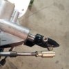
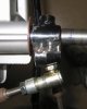
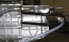
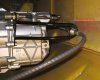
I've been working with Jim from CableShift on a prototype for the "Fran-Kin Box" shortened G50. Jim designed the prototype around the shortened G50/03 that he had in his shop. Jim sent me the prototype to check compatibility with my G50/20. It was a very close fit, but did take some minor grinding and bending to get a good fit. Compared to what I've seen others do to make the stock shifter bracket work, it was a breeze by comparison.
I mocked up a cable coupler, by cutting and tack welding a stock coupler together. It works well and the cable angles are good, but Jim is concerned that the fore/aft cable may put too much side force on the shift rod. Jim is sending me a GTM setup to try that places the fore/aft cable at the 11:30 position.
Jim plans to use feedback from me an others to eventually put the "Fran-Kin Box" shifter into production. I think this is very encouraging news!
I'll keep you posted
Attachments
Glad that you were able to get them to work with you. I couldn't get them to phone or email. If they had I would have shared the work that I ended up doing with them.. Of course they may well have called it rubbish too.. Oh well...
I would lock that shift lever to the shaft and actually run everything through it's full range of motion via the shifter before you call it good. I found that the cables work well until you get close to the bind point where they start to stiffen up considerably.
I would lock that shift lever to the shaft and actually run everything through it's full range of motion via the shifter before you call it good. I found that the cables work well until you get close to the bind point where they start to stiffen up considerably.
Incredible pictures Bill.
VintageAir evaporator
The VintageAir evaporator (air handler) is supposed to be mounted to the underside of the dash/foot well aluminum structure on the passenger side. That puts the air handler in a "Knee knocker" position for the passenger.
I'm looking for alternatives:

The VintageAir evaporator (air handler) is supposed to be mounted to the underside of the dash/foot well aluminum structure on the passenger side. That puts the air handler in a "Knee knocker" position for the passenger.
I'm looking for alternatives:
- I've seen PICs where a large hole was cut in the upper foot well aluminum structure so the entire VintageAir air handler can be moved up to use the space under the fiberglass dash panel. That seems like a lot of structure to cut away, so that makes me nervous.
- The foot well is very deep toward the front and would be a good place to stuff the air handler. However, the VintageAir system that comes with SLC kit doesn't really fit there either. Another choice is a smaller unit like the Hurricane evaporator. I would fit nicely if you remove the plenum on top.
Dave Lindemann
Lifetime Supporter
Re: VintageAir evaporator
Bill - It looks like they have a test fit case that would allow trial fitting the evaporator without spending a few hundred $$. Looks like a nice compact unit.
Dave L
Bill - It looks like they have a test fit case that would allow trial fitting the evaporator without spending a few hundred $$. Looks like a nice compact unit.
Dave L
The VintageAir evaporator (air handler) is supposed to be mounted to the underside of the dash/foot well aluminum structure on the passenger side. That puts the air handler in a "Knee knocker" position for the passenger.
I'm looking for alternatives:
Any advice?
- I've seen PICs where a large hole was cut in the upper foot well aluminum structure so the entire VintageAir air handler can be moved up to use the space under the fiberglass dash panel. That seems like a lot of structure to cut away, so that makes me nervous.
- The foot well is very deep toward the front and would be a good place to stuff the air handler. However, the VintageAir system that comes with SLC kit doesn't really fit there either. Another choice is a smaller unit like the Hurricane evaporator. I would fit nicely if you remove the plenum on top.
Ken Roberts
Supporter
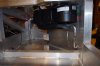
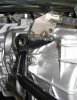
The factory AC evaporator unit mounts in front of your legs and nowhere near your knees. I'm 6'1" and my seat is in the rear most position. Here is a couple of pictures without the dash installed. There is no interference at all with the legs!


Vintage air unit mounted high in box with outlet cut-outs above in the alum. tub to round ducting.
BTW: As a service message to my fellow SLC'ers I'll take this opportunity to give my personal opinion regarding a car A/C vendor who's dealings have been less than stellar - and I'm being nice with that comment - Nostalgic Air Parts - which also includes their sister companies: Jeepair.com, Coldhose.com, Britishac.com & Nostalgicplastics.com
Caveat emptor -- sorry about the slight hijack, I wanted to save others from the heartbreak....
Attachments
Last edited:
Ken Roberts
Supporter
Thanks for the heads up Mike as I still need to buy various fittings to complete my AC install.
I guess I like plenty of room under the dash to flail my legs.
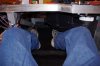
On the driver's side, my big feet hit the steering column tilt/telescoping actuator motors.
On the driver's side, my big feet hit the steering column tilt/telescoping actuator motors.
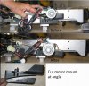
- The tilt motor on the right side hangs down further and is the most noticeable. This motor is mounted on a long plastic arm that moves in and out with the telescoping motion. I cut a section out of the arm and replaced it with some 1/8" x 1" steel strapping. The steel strapping can then be bent to move the motor up and away from you feet. The material that the plastic arm is made from is designed to take self tapping screws, so place your screws where they will get the most plastic to bite into.
- The left telescoping motor doesn't hang down as far, but you can still hit your feet on it. This motor is attached to the column via a plastic mount. Cutting the plastic mount at an angle moves the motor up and out of the way.
Attachments
Last edited:
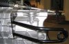
Yesterday, I took advise from the Book of Zoey. Dang, that sounds reverent, doesn't it.:bow:
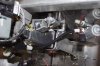
If you intend to heel/toe your brake/throttle, you may hit your feet on the aluminum case at the end of the column. That end of the aluminum case serves no purpose in the SLC, so I cut it off.
If you haven't been out to Zoey's personal build forum lately, you should go visit it. Zoey is making significant progress and his forum has lots of great tips.
Attachments
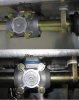
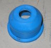
While I had the steering column out, it was a good time to seal the gap between the tub and the steering rack. I had a ball joint boot laying around in my garage and found that it fits the gap perfectly. Just cut off the top off the hat.
Attachments
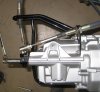
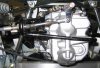
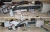
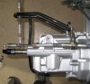
I'm still working with Jim at Cableshift on the "Fran-kin Box" prototype for the shortened G50.
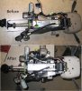
I installed the SLC body tail section to check clearance to the prototype bracket.
I installed the SLC body tail section to check clearance to the prototype bracket.
- The right/left cable portion of the bracket hits the tail section. It pushes the body out ½”, so the bracket needs to be shortened by ¾” to allow some clearance.
- There is about 2” clearance between the SLC body and G50/20 case at the shift rod seal. Is this what you are seeing as well?
Attachments
Yesterday, I took advise from the Book of Zoey. Dang, that sounds reverent, doesn't it.:bow:
If you intend to heel/toe your brake/throttle, you may hit your feet on the aluminum case at the end of the column. That end of the aluminum case serves no purpose in the SLC, so I cut it off.
If you haven't been out to Zoey's personal build forum lately, you should go visit it. Zoey is making significant progress and his forum has lots of great tips.
Some excellent documentation in this tread Bill.
I had made the mods that the Zoey photo shows, but I have found the limited adjustment range of the column due to some interference with the dash and turn signal stock makes the fore/aft adjustment of lesser value. I also find that I prefer the vertical adjustment to be full north. So for me I think I will eliminate the motors and the complexity and just turn the cables by hand if I need or want to reposition the wheel on occasion.
BTW: I also found Jim @ Cableshift to be interested and very helpful with my Ricardo cable tuning.
Last edited:
BTW: I also found Jim @ Cableshift to be interested and very helpful with my Ricardo cable tuning.
What cable tuning with the Ricardo? My experience was that it worked perfectly right out of the box, with the worst being that shifting out of 5/6 don't cause the shift lever to automatically return to centering over 3/4 because of lack of a return spring.
Similar threads
- Replies
- 26
- Views
- 8K
- Replies
- 7
- Views
- 6K
- Replies
- 4
- Views
- 10K