Rcr 40-31

Chris Kouba

Supporter
Can anyone help me figure out why the standard bracket from RCR won't fit on my motor?

Add'l pics here:

Picasa Web Albums - Chris Kouba - 2010-10-12

It is a Ford Motorsport 302 crate motor (6007-xb3). The spacing on the water pump doesn't match up with the spacing on the RCR bracket. Any ideas?

ac%20hanger%20002.jpg


IMG_1066.JPG


ac%20hanger%20001.jpg
 
Hi, looks to me that you have a ford explorer front dress setup 94 and up, and the ac bracket was setup for a 93 and down sbf .
regards Bob
 

Chris Kouba

Supporter
Thanks Bob.

So my next question is has anyone found a bracket for the Explorer front end which works with an RCR?

A bracket of my own manufacture may look a little out of place on this car but I'm not afraid to try.

What I want to avoid is the interminable chase of something that works...
 

Fran Hall RCR

GT40s Sponsor
Chris,

my suggestion would be to mock up the bracket on the fasteners that do line up with the brakcet....with the mismatch bolt removed .

Then attempt to mark the new hole, drill/file it open to the correct location.

Then weld a washer onto the bracket to create the new hole location...neat, clean and a lot less work than making a new bracket.
 

Chris Kouba

Supporter
Thanks Fran.

The plate sits about 1/2" fwd of the water pump also- effectively just needs to be welded at a different "depth" to sit flush against it. Any chance when you get your next batch laser cut that you could send me a box with the parts in it unwelded and I'll burn them together on this end?
 

Chris Kouba

Supporter
Progress?

So the RCR bracket didn't fit and would likely not look too sweet all hacked up and Frankensteined so I thought I'd try my own. Check out what I came up with:

IMG_2541.JPG


OK, so it looks like a POS too but this is really what I wanted to check:

IMG_2542.JPG


At this point I have a slab of alu and a drawing and now a model of what I want. I also have a friend who offered the use of his mill/lathe/machine shop so this was built as a POC (proof of concept) to validate the compressor will fit in the space afforded. So far it looks good, though I have no idea when I might be able to actually start cutting metal.

Anyone with an RCR, see any issues with the location? Output port locations? Hose lengths? Anything I am missing?
 
Last edited:

Chris Kouba

Supporter
PROGRESS!!!

I was permitted to indulge myself for Christmas:

IMG_2574.JPG


So I picked up this:

IMG_2584.JPG


Made a huge mess:

IMG_2586.JPG


And now have something functional:

IMG_2593.JPG


It still needs to be made aesthetically pleasing and all the excess stuff needs to get trimmed off but I am incredibly excited to have something I made that looks reasonably appropriate (half the car is billet after all!) hanging the compressor in the proper position.

I had only used a lathe and a mill once during freshman year in college. I think it came back to me enough, although I probably am a little overly proud of it right now.

Once this is in and finalized, I will be able to final set the motor/trans and get going with the rest of the build. Understatement alert: Looking forward to that!

All the best,
 

Randy V

Moderator-Admin
Staff member
Admin
Lifetime Supporter
HOLY SCHNIKES Chris!!!!

I think they should have hired you to build the new 35W Bridge here in Minneapolis!!!

I just love standing knee deep in chips at my mill and lathe....
 
Hi Chris

nice toy, please tell me that this is not solid and you took some of the material out from the other side.

If you take the contours of a little, it will be looking nice additionaly to the for shure perfect function.

Well done

TOM
 

Chris Kouba

Supporter
Relax guys, I think you guys missed where I wrote this part:

It still needs to be made aesthetically pleasing and all the excess stuff needs to get trimmed off...

There is still *significant* trimming which needs to be done. I was just excited to validate that all the holes were in the proper positions and stuck it on the motor to see it all in place.

Fear not, the finished product will look appropriate for the car.
 
Oh am I jealous. First, because you will be able to get at your compressor without removing the engine (mine is buried in the chassis) and second because you got to machine a brick of aluminum where I pretty much made everything out of Home Depot angle with a drill and saw.

That's going to be an extra sweet piece, just for all of that. Maybe a plexi window so you can see if from the cabin :)
 

Chris Kouba

Supporter
I am calling this finished now:

IMG_2597.JPG


IMG_2606.JPG


IMG_2608.JPG


I'm probably a little prouder of it than I should be but it's been a lot of work and a great learning experience. Some of my radius work could have been better but I am really stoked with it anyway. I should really wait til the belt is on and validate that it really is as well lined up as I think it is before really celebrating.

At this point I need to go find a little more billet to make the tensioning side. This is GREAT fun!
 

Jim Rosenthal

Supporter
Chris, did you do a wooden proof or anything like that to verify the tool paths, or did you just go for it? I am very impressed. Is that mill computer controlled or are you the computer yourself?
 

Chris Kouba

Supporter
Thanks gents. I was shooting for something pro-looking and I am pleased on all counts. It's neat to think you can do something but it feels spectacular when you actually go pull it off.
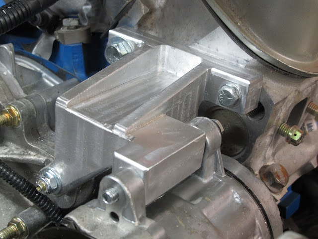
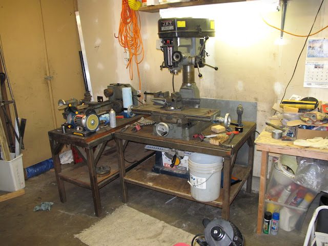
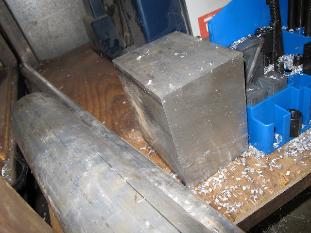
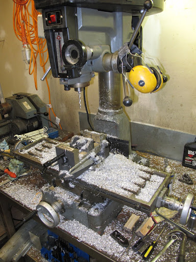
Jim- The mill is completely manual and the chunk you see in the pics was the first thing I cut with it after picking it up a few weeks ago. I thought about getting some plastic or wood to try first but in the end just went for it. I tried to think about tool paths in advance but would have to say I get a "B-" or so. With the way I cut some features, I had a tough time with the radiusing of the corners (was basically impossible with my resources) and in the end was able to cut out most of the mistakes I made. I was smart enough to start with the bottom side...

I did a bunch of sketching with Sketch-Up (more of an illustration package, free from Google) just to have an idea of what it'd need to look like in the end and that was about it. That sketching and the little steel mock up I made earlier were my two key items. After having a physical proof of concept to measure off and "seeing" a full rendering in Sketch Up, I was able to fill in the rest of the details when cutting metal.

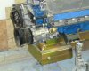
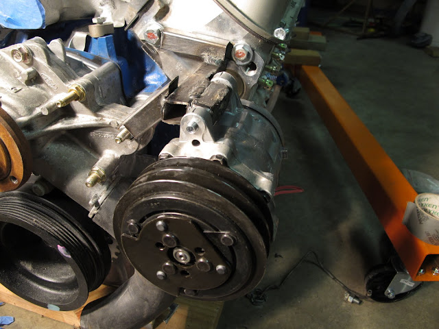
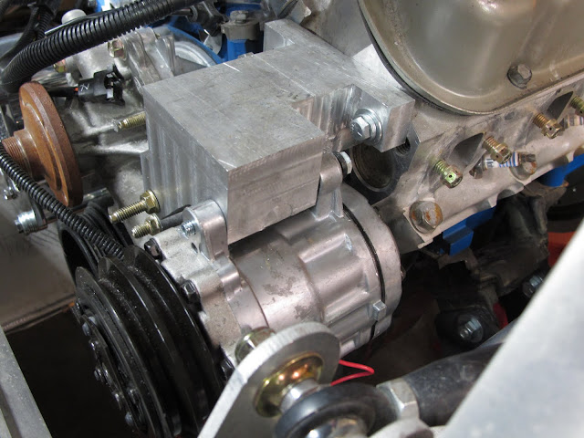
At this point I will be going through the rest of the pulleys and lining everything up and once that is set I will FINALLY be able to set my motor in its home position. I am somewhat close on wiring, just need to sort the bladders, fuel systems, starter, clutch, brakes, shifter...

Won't be long now!
 
Back
Top