
You are using an out of date browser. It may not display this or other websites correctly.
You should upgrade or use an alternative browser.
You should upgrade or use an alternative browser.
Rcr 40-31
- Thread starter ckouba
- Start date
Nicely trimmed out, you got the fat out that bracket.
Cheers,
Howard
Cheers,
Howard
Chris Kouba
Supporter
More glacial progress...
Today, for the first time ever, I had all the ancillaries mounted and belted and fitting in the engine bay. Follow along:
All the things attached to each other-

All those attached things resting in the engine bay, without interfering with the chassis (YAY!)-

Not visible are the engine mounts which have been bolted in to the chassis.
Got to use my cool new power tools a few more times. Reworked compressor bracket due to the thickness of the new water pump-

Turned out some spacers to take the place of the 10 pound stacks of washers used to space the transmission-

Cut out the second half of the compressor hanger project (the tensioner bracket)-

All the stuff resting together happily-

I've been ridiculously busy with other stuff but am starting to build momentum back into the project. It feels great to walk away without a headache!
Need to validate coolant hose routings and such and make sure everything is actually going to line up, then it's back at it with the wiring and other systems to bring the thing to life. I am starting to get excited about it again.
All the best to the gang.
Chris
Today, for the first time ever, I had all the ancillaries mounted and belted and fitting in the engine bay. Follow along:
All the things attached to each other-
All those attached things resting in the engine bay, without interfering with the chassis (YAY!)-
Not visible are the engine mounts which have been bolted in to the chassis.
Got to use my cool new power tools a few more times. Reworked compressor bracket due to the thickness of the new water pump-
Turned out some spacers to take the place of the 10 pound stacks of washers used to space the transmission-
Cut out the second half of the compressor hanger project (the tensioner bracket)-
All the stuff resting together happily-
I've been ridiculously busy with other stuff but am starting to build momentum back into the project. It feels great to walk away without a headache!
Need to validate coolant hose routings and such and make sure everything is actually going to line up, then it's back at it with the wiring and other systems to bring the thing to life. I am starting to get excited about it again.
All the best to the gang.
Chris
Looking good! !
Question: is it better to use all three pulleys for the AC belt or just the lower pulley? If one uses just the lower crank pulley the belt will have more contact area on the AC pulley and thus be less likely to slip, it would seem.
Mine is arranged the same as yours, but it just occurred to me that it may be better to run it off the crank pulley without the water pump pulley. That AC compressor pulley does tend to slip if it is not pulled really tight.
Chris Kouba
Supporter
Gents, thanks for the words of encouragement. It's been a long road to here and it's not over yet. Tom, your car is looking fantastic. Congrats on a job extremely well done! Chuck, yours has looked fantastic for a while now. I am extremely jealous of both of you. Randy, I can't confess to checking in on your build lately but I'm sure you're making progress as well.
As for the belts, I did go down that road. The AC belt ended up in contact with the bottom fwd face of the water pump pulley. I had to swap out for a dual groove water pump pulley and re-route. Now that it's all done I may go back out and validate it still doesn't work.
Chris
As for the belts, I did go down that road. The AC belt ended up in contact with the bottom fwd face of the water pump pulley. I had to swap out for a dual groove water pump pulley and re-route. Now that it's all done I may go back out and validate it still doesn't work.
Chris
Chris Kouba
Supporter
Nothing glamorous to show for it but have been able to spend a bit of time on the GT recently.
The clutch is in and appropriately set (I think).
Bellhouse and gearbox installed.
I grabbed a socket and wratchet and turned the crank and watched the trans output flanges rotate!
Starter installed.
And the most exciting thing for me, I only have a couple more wires to connect (literally- just 2) and I think the motor is wired.
The most rewarding part- I connected a spare trailer marker light to the coil 12+ wire and the starter solenoid wire to the solenoid. I wired a 12V supply to the fuse block. I then turned on the ignition- the light went on. Turned the key... CLICK!!! Contact in the solenoid!
Only a couple more things to do before I can actually start it, and of course it's currently only air cooled. But not having done anything like this before, it's HUGE- I feel like I've turned a major corner!
Ron McCall
Supporter
Congrats!!! Won't be long now!!!
Chris Kouba
Supporter
Congrats!!! Won't be long now!!!
With the way life works out, that's been wildly optimistic. I have been making occasional progress on the car though, most notably on the cooling system.
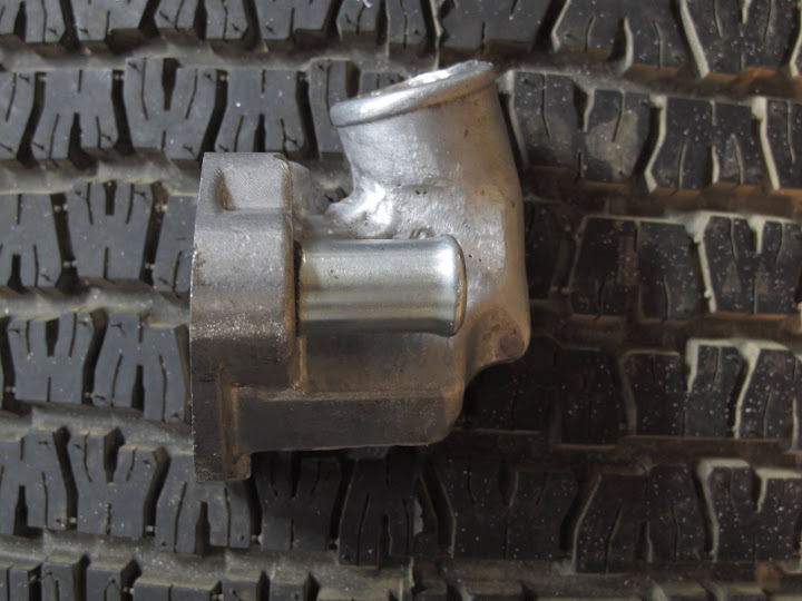
First step was a thermostat cover/water outlet. In an act of blatant plagiarization, I found the same part that Chuck and Ryan had used, except stumbled upon one in aluminum. It didn't fit the space (as expected) but I had a plan- there was enough stock on the face to mill the mating surface at an angle and hopefully re-direct the outlet hose sufficiently way from the firewall.
I chucked it up on the mill and gave it a shot. The verdict? Nope.
I milled in the thermostat recess (I picked up a rotary table for the mill too!) and though about it again- "What would Chuck do?" I didn't have to think too hard about it as he has documented extremely well what he has done. I brought it over to the band saw and sliced out a similar wedge as he did.
In what I will term "the off season", I picked up a new welder- an AC TIG box- and I have been slowly teaching myself to weld alu. It's been an interesting process as I do have some (a minor amount of) prior TIG experience and enough knowledge to be dangerous. After puddling many off-cuts in search of fusion, I eventually got the hang of it and tried my hand at the water outlet (It was only $9 at the local Napa).
There was a bit of porosity in the parent metal but I managed to do a reasonable job stitching it back together. A little cosmetic touch up with the belt sander and it'll look reasonable:

I took the liberty of blocking off and pressure testing it with soapy water and compressed air. I did have a few pinholes in the porous area but went back and filled them back up.
Subsequently I have also dabbled in stainless (no pics up yet) to fab some hard lines for the coolant to get past the headers (more plagiarization from Chuck). That went reasonably well, sticking together .065 wall tubing without burning through. There were some areas where my welding did neck down the joint but as it's not a structural member, I will leave well enough alone.
I also fabbed up the connecting pipes connecting the rad to the pipes in the spine. They look remarkably like Chuck's...
Apart from hoses to connect everything, all I think I need is the surge tank and coolant reservoir. I have been toying with the idea of actually making my own tanks as a learning experience- I know the filler necks are available and have a bunch of thick sheet off-cuts to play with. We'll see where my motivation level lies as we make it through the holidays.
Best wishes for a happy holildays and a great 2012!
Chris
PS - Pictures from a recent distraction in November, if you're interested:
Mountain biking in Moab, UT
Bryce Canyon Nation Park
Chris: You did such a beautiful job duplicating our first thermostat cover I am somewhat reluctant to post this post. Long after that project we discovered a problem, which was referenced in a much later post. Here it is:
Thermostat housing. Recall all the trouble we went to having a generic thermostat housing cut and welded back together so it would fit? When we got the car running it leaked antifreeze. After a lot of searching for the leak, replacing the gasket without success, and a bit of colorful language, we discovered the problem. The bypass opening on the back side of the thermostat housing was almost ¾ inch but the opening on the manifold was half that size. There was not enough surface area to obtain a seal. A metal gasket with a smaller hole could have been fabricated, but we instead pulled off our parts shelf a nice CSR thermostat housing, Part # 9111C, which we bought a long time ago but did not think would work. It is a very nice piece, machined from aluminum using O rings to assure a good seal. The outlet can be moved from one side to the other. We tried it and it fit very well. And it looks a lot nicer. It is a bit pricey (around $100 as I recall) but worth it.
Perhaps your housing did not have the oversized bypass opening or alternatively you could fabricate a metal washer. Keep the posts coming. You are making good progress.
Chuck
Attachments
Chris Kouba
Supporter
Chuck-
Thanks for the heads up. Please do not hesitate to post (or any one else) if I might be heading astray. I've been away a few days but will check out the bypass holes next time I'm in the shop. Worst case, it's been a good learning experience as it was the first aluminum thing I welded for the car. Best case is it'll work...
Thanks again and Happy New Year!
Chris
Chris Kouba
Supporter
Been busy in the shop-
Hard pipes mentioned in previous post:

My own custom expansion/header/purge tank, in excruciating detail:
From the lathe:

Starting point:

Partway:

One hose connection installed:

And the other:

I know this stuff isn't groundbreaking, but it is for me. The tank will fit snugly in the space between the main roll hoop and the passenger side aft brace.
I am still waiting on the radiator cap attachment so I can finish it off, but I am happy with it so far. I am definitely getting more comfortable with welding on aluminum and am enjoying the end result enormously.
Chris
Hard pipes mentioned in previous post:
My own custom expansion/header/purge tank, in excruciating detail:
From the lathe:
Starting point:
Partway:
One hose connection installed:
And the other:
I know this stuff isn't groundbreaking, but it is for me. The tank will fit snugly in the space between the main roll hoop and the passenger side aft brace.
I am still waiting on the radiator cap attachment so I can finish it off, but I am happy with it so far. I am definitely getting more comfortable with welding on aluminum and am enjoying the end result enormously.
Chris
Chris
i´m impressed . nice aluminium welding. Can you show a picture where your put your tank.
Your car has the standard role hoop behind the firewall in the engine compartment correct ?
if the second hose connection is for the purge line it looks rather big. Use max an AN3 line for the purge lines from rad and engine
TOM
Chris Kouba
Supporter
Thanks Tom.
I didn't take a picture of it in place yet as I still need to cook up some mounting hardware. It'll be hung on the rear brace for the main hoop on the right side of the engine bay (look closely for the red line drawing):

The roll hoop isn't the RCR product but one of my own. Pics are earlier in the thread, but at this point I have snipped the front half of it off due to the other dialogs about potential head contact with full cages in a 40.
I didn't take a picture of it in place yet as I still need to cook up some mounting hardware. It'll be hung on the rear brace for the main hoop on the right side of the engine bay (look closely for the red line drawing):
The roll hoop isn't the RCR product but one of my own. Pics are earlier in the thread, but at this point I have snipped the front half of it off due to the other dialogs about potential head contact with full cages in a 40.
Chris Kouba
Supporter
if the second hose connection is for the purge line it looks rather big. Use max an AN3 line for the purge lines from rad and engine
I'm not sure what AN3 converts to but I sized the connections based on Chuck's build, which had a 3/8" line from the rad in the front to the top of the tank.
The bottom fitting is for a 5/8" hose and will connect directly to 5/8" fitting on the water pump next to the thermostat bypass.
The only other connection will be from the pressure cap fitting, another 3/8" line to an overflow reservoir.
I actually looked a while ago and if I remember correctly, yours is set up in a similar manner, is it not?
Dear Chris
i also have answered on your other post with pictures of my setup.
AN 3 is app 1/8" inner diameter. I thin 3/ 8 will ne to big bypassing to much fluid. It does not need a big diameter to get the air out. CHeck out RON EARPS LOLA tread, he has sued a bigger purge line first and than switched to a smaller one later, because of issues.
Also if a remember Chucks build correctly, he has put reducers into his purge lines to minimize flow.
TOM
Hi Chris, Nice welding.
I have just purchased a new Cebora AC / DC tig 220 amp single phase welder so that I can teach myself aluminium and stainless welding.
I'm OK with Mig but ally is like brazing and takes a bit more care as you probably have found out.
Using thicker sheet reduces distortion, so I'll start off thick, literally
"Excuss the pun "
I have Got lots of ally to mess up.
Nice job, nice car
Cheers