Can You give me some feedback on the Hurricane unit over the unit supplied by RCR? If your car was not delivered for another 6 weeks, would there be benefits to consider that unit instead?

- Forums
- GT40 Replica Manufacturers' Corner
- RCR Forum - RCR40/SLC/917/Superlite Aero
- The SLC Clubhouse
You are using an out of date browser. It may not display this or other websites correctly.
You should upgrade or use an alternative browser.
You should upgrade or use an alternative browser.
Rumbles SLC Build
- Thread starter rumbles
- Start date
-
- Tags
- g50 gear ls3 powernation rumbles slc superlight yellow
not Phsyically inside the cabin though? I'm assuming he meant stickign the battery like in the passenger footwell infront of the person's feet. :/
The Mercedes E Class (W210) has the battery mounted under the rear seat.
OK then, based on experience with them (all motorcycle) I had it in my mind that a sealed battery (Braille) meant just that. But based on comments here that may not be the case. So production cars with the battery in the area must have sealed compartments for them (?) I may need to fabricate a sealed and vented battery box to address this issue. Thanks for the clarifications Gents.
I return you now to Bill's regularly scheduled build thread....
I return you now to Bill's regularly scheduled build thread....
Under normal conditions, any gas produced during the charging of a SVR (sealed valve regulated) battery, such as an AGM (absorbed glass mat) battery, will not reach sufficient pressure to get by the battery's safety regulator valve. It is only when these batteries are severely overcharged that gas ventilation becomes a concern. If you were to use one of the more sophisticated battery chargers/voltage regulators that are commonly used on boats with large banks of these batteries, then the batteries shouldn't ever vent gas (but there would be other issues involved in integrating the rest of your electrical system components into this kind of charging environment.) If you use the simple voltage regulation scheme common in cars (and especially if that voltage is set too high), then battery abuse and venting could become an issue even with sealed batteries.
Yup, and you'll smell the rotten eggs odor long before the hydrogen-sulfide concentrates enough to become dangerous.
Earlier I was joking about your cloths rotting. Long ago in the Air Force, I worked in a shop that serviced batteries for military aircraft. There were always 10-30 huge lead acid batteries being heavily charged at a time and boiling up gobbs of hydrogen-sulfide. No matter how many exhaust fans and safety gear you wore, a pair of cotton fatigues would barely last a week.
Earlier I was joking about your cloths rotting. Long ago in the Air Force, I worked in a shop that serviced batteries for military aircraft. There were always 10-30 huge lead acid batteries being heavily charged at a time and boiling up gobbs of hydrogen-sulfide. No matter how many exhaust fans and safety gear you wore, a pair of cotton fatigues would barely last a week.
Last edited:
Howard Jones
Supporter
Alex...........calling people stupid isn't going to elicit a lot of sympathy for your cause when you post something unsupported with logical imperial data that the rest of us would like to offer useful friendly advice about.
See how nice that was.
See how nice that was.
Today's post is brought to you by the word "Stover".
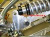
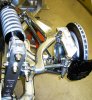
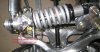
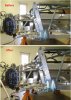
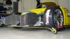
I finished the rear suspension.
As I was pulling the suspension apart, I noticed that the bolt for the rear of the chassis brace was captured by the cap screw that secures the shock. That means the shock must be disassembled to remove the chassis brace. To fix that I cut the excess length off the bolt, I flipped it around, and then used a narrower "Stover" lock nut.
There seemed to be limited travel in the rear suspension:
I finished it off by sanding and polishing the a-arms in the rear as well...Bling!
I finished the rear suspension.
As I was pulling the suspension apart, I noticed that the bolt for the rear of the chassis brace was captured by the cap screw that secures the shock. That means the shock must be disassembled to remove the chassis brace. To fix that I cut the excess length off the bolt, I flipped it around, and then used a narrower "Stover" lock nut.
There seemed to be limited travel in the rear suspension:
- When in full drupe, the shock was interfering with the bell crank, so I ground away part of the crank.
- When fully compressed, the shoulder on the misalignment spacers were the problem again. As with the front suspension, I ground down the spacer side contour.
I finished it off by sanding and polishing the a-arms in the rear as well...Bling!
Attachments

Last edited:
Ken Roberts
Supporter
Bill the stover lock nut MUST have the threads of the bolt completely pass thru it to be effective . The end of the nut is slightly oval (distorted). This area is the "locking" feature.
For extra insurance if you choose to leave it as is I'd use red or blue locktite on the threads.
For extra insurance if you choose to leave it as is I'd use red or blue locktite on the threads.
Last edited:
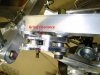
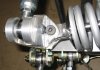
I left the bolt in the stock position, but made a large 2-nut "washer" which I used to hold the safety wire that is keeping the nuts from backing off.
I like safety wire, and have used it extensively in the car. It gives a nice visual view of the condition of the fastener.
I like safety wire, and have used it extensively in the car. It gives a nice visual view of the condition of the fastener.
Bill,
Ken and others are absolutely correct....thread must come through the nut...as an ex aviation tech I am a little surprised that you dont have a at least one thread showing everywhere.
Ken and others are absolutely correct....thread must come through the nut...as an ex aviation tech I am a little surprised that you dont have a at least one thread showing everywhere.
You are correct, that an aircraft quality check would flag it on a visual inspection.
The threads are not quite thru the nut, but I can tell you that it is thru enough to grab plenty of the locking end of the nut. I know its safe, but I can understand how it would make others nervous.
I replaced it with a slightly longer bolt...Don't tell my commanding officer.:lipsrsealed:
The threads are not quite thru the nut, but I can tell you that it is thru enough to grab plenty of the locking end of the nut. I know its safe, but I can understand how it would make others nervous.
I replaced it with a slightly longer bolt...Don't tell my commanding officer.:lipsrsealed:
Attachments
Last edited:
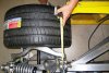
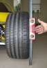
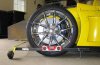
I finished my 4 wheel alignment.
I've seen lots of post for various ways to do an alignment. Here's my "down-home" alignment method. I get consistent results, but some of you hard core racers may want to turn away from your PC screen now.
All you really need is:
I've seen lots of post for various ways to do an alignment. Here's my "down-home" alignment method. I get consistent results, but some of you hard core racers may want to turn away from your PC screen now.
All you really need is:
- Some string
- 2 angle Irons
- Tape measure
- Digital level
- Caster: Fran tells me that both the front and rear suspension geometry is setup with the 5 degree caster. As long as both a-arms have rod ends with about the same number of threads showing (front to rear), you will be very close to 5 degrees.
- Camber: -1 degree camber can be measured with a digital level. Just place it on the sidewall of the tire, but back a bit from the bulge of where the tire contacts the floor. On my SLC, I needed to adjust the front upper a-arms out about 7 turns. The rear needed no adjustment. Be sure to check the that rod end threads still has the minimal safe depth via the peep hole on the under side of the a-arm.
- Toe: Hang the angle iron over each tire using a piece of string. They should be hung so they are level, centered on the tire, and at a height that is higher than the bulge of the tire contact patch, but below the floor pan. This ensures the angle irons sit squarely on the tire and are at a level where you can measure the left/right distance under the car. You are looking for a slightly smaller measurement on the front vs the back of the tire for "Toe-in".
- On the front, adjust the steering rod ends to get in spec.
- On the rear, I found it easier to first adjust the overall toe using the stationary steering rod ends behind the spindle. Then you need to ensure the toe is centered on the frame. Just pick an easy reference point from the tire to the frame and ensure the distance is the same on both sides by turning the stationary steering rod ends an equal number of turns on both sides. Then double check your Toe to ensure it's still in spec.
Attachments
Last edited:
Dr. David
Lifetime Supporter
May I make a suggestion?
There is a great tool that allows you to do this without hanging angle iron with strings. I also takes into account that most, if not all, garage floors are not level. It is the Tenhulzen wheel alignment gauge manufactured by Tenhulzen Automotive. It is very accurate and also very cost-effective. You can even change your set-up in the pits on track days, and you can fold it up and put it in you tool box. The optional frame allows you to quickly perform your toe set-ups according to the vehicle's centerline. You can even use it when your car is on a lift.
Check it out: Tenhulzen Automotive
David
I plumbed my brake system and filled it with fluid. The reservoirs and lines sealed up nicely. However, I have leaks at numerous brake line connections.
Is anyone else see that as well?
I'd just tightened them down further - one is conforming soft metal to metal- unlike an accurate angled AN fitting -- IMO.
Last edited:
Similar threads
- Replies
- 26
- Views
- 8K
- Replies
- 7
- Views
- 6K
- Replies
- 4
- Views
- 10K