
You are using an out of date browser. It may not display this or other websites correctly.
You should upgrade or use an alternative browser.
You should upgrade or use an alternative browser.
Rob's RCR40 Build
- Thread starter VintageVenom
- Start date
Rob
Lifetime Supporter
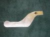
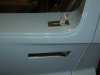
Finished up the door hardware today. Fabricated a couple handles and plates.
Attachments
Last edited:

Beautiful, Rob.
As a thought, are you planning on making it lockable?
Dalton
As a thought, are you planning on making it lockable?
Dalton
Rob,
I'm following your build closely as we seem to have a very similar build, including RHD. I got my kit yesterday and have beeen busy taking it apart. I was looking at the dash board and trying to figure out how the dash and roll cage can fit as cleanly as you have it in your second to last picture. What's your secret and can you post any closer pictures?
I'm following your build closely as we seem to have a very similar build, including RHD. I got my kit yesterday and have beeen busy taking it apart. I was looking at the dash board and trying to figure out how the dash and roll cage can fit as cleanly as you have it in your second to last picture. What's your secret and can you post any closer pictures?
Rob
Lifetime Supporter
Ticked a few more items off the white board this weekend. Man..I wish every weekend was four days....
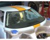
Defroster vent painted and installed...check
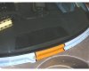
Windshield....check
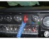
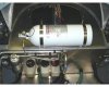
Fire system...check
Speedo sensor wiring...check
A/C hot water gate and cable...check
and a few other odds and ends I can't recall at the moment or not worth mention.
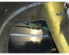
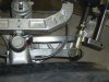
Bill last few pics are the shift cable system you requested.
Defroster vent painted and installed...check
Windshield....check
Fire system...check
Speedo sensor wiring...check
A/C hot water gate and cable...check
and a few other odds and ends I can't recall at the moment or not worth mention.
Bill last few pics are the shift cable system you requested.
Attachments
-
 P1120259.jpg28 KB · Views: 1,161
 -
 04_windshield.jpg53.3 KB · Views: 1,169
 -
 09_windshield.jpg29 KB · Views: 1,743
 -
 fire_system_06.jpg64.4 KB · Views: 1,195
 -
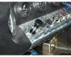 19_cable02.jpg60.5 KB · Views: 1,141
 -
 19_cable01.jpg64.8 KB · Views: 1,160
 -
 fire_system_03.jpg43.4 KB · Views: 1,125
 -
 19_cable04.jpg40.3 KB · Views: 1,156
 -
 P1120378.jpg62.8 KB · Views: 1,218
 -
 P1120321.jpg44.6 KB · Views: 1,139
 -
 P1120322.jpg46.8 KB · Views: 1,182
Last edited:
Rob,
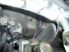
On your fouth picture posted above, (showing the inside of the door and latch assembly showing the cap screw ie: bolt holding the outside door latch),.....would it be a good idea to build up the fiberglass area that the bolt shoulder surfaces mate to, so the bolt shoulder rests on a flat fiberglass shoulder?
Just a thought, and I hope my info above makes sense to you.
Fantastic craftsmanship, and I love the Gulf colors. Keep the pictures coming...great job!!!!!!
Hi Rob,
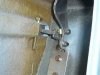
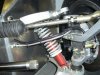
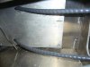
Your car looks great and nice job. I just notice one thing that looks a little hazardous on the picture with the brake-lines at the front. It seems that the brake-line possible ( if unlucky ) can get stucked in the springs. Suppose you brake and turn at the same time and for some reason things get moving ( and they sure do on the track ) you can get into a situation where you might loose the the brakes on one wheel - not good!
I did that mistake when I did build my Seven but luckily the inspector identified it and it was easy to correct.
Keep up the good work!
Best regards
Henrik
Tom,
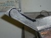
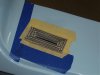
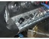
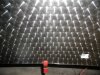
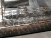
The finish he has looks very much like "engine turning". It is accomplished with a drill press, a polishing disc, and WD40. I found the disc at Harbour Freight. the finish is one of old school expensive cars of the 20s-30s, It is also a finish that is applied to very expensive gun barrels using tiny disc. Usually done on a slide shelf so that the rows can be setup equal to the radius of the last row. The design is a repeating pattern that is shifted off center from the row above it. The variations are endless. Just have to be careful about heat build up and warpage.
Bill
Attachments
Rob:
Great pictures, and great work. Your pics have answered some questions I had on some details - like mounting the speedometer pickup. Keep those great pics coming!!
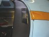
Question: you have a nice trim strip of something between the dash and the spider, filling that nasty gap. What is it?
Chuck
Great pictures, and great work. Your pics have answered some questions I had on some details - like mounting the speedometer pickup. Keep those great pics coming!!
Question: you have a nice trim strip of something between the dash and the spider, filling that nasty gap. What is it?
Chuck
Rob
Lifetime Supporter
Hi Guys,
Thanks for the positive comments.
Bill.....you're giving away my secrets man...!!! Actually, dead on. That is exactly how I do it.
Chuck, I used end bulb weather stripping Worked quite well.
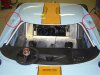
Henrik, Thanks for the input. I think it's a perspective thing in the picture. I perform an extensive fully articulated jounce and rebound assessment on all my builds for just this concern. See pic below. Thanks again...
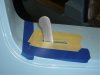
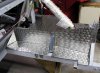
Richard, Actually, no not planning on it. Reasoning, the shift cables shown are open to elements inside and out of the chassis. So, no value in doing so for sealing purposes and I have no abrasion concern as the alum is an inch thick and deburred/polished smooth. Regarding the speed sensor, the convolute is an interference fit to the hole, which is again deburred and 1/4" thick. I almost grommeted the speed sensor. With the drill in my hand, I decided I just couldn't drill a hole so far over-sized just for the grommet, when I really couldn't justify the need for it. - Always looking for a new or better way to suck eggs, so no issue mate....
Gary, I think you're talking about the pivot pin for the exterior handle. The bolt is temporary until I spin up a set of pivot pins. Once done, there won't be the overhang to consider. Aside from that, I honestly don't think there is a load concern. Not much effort is needed for the doors to pop, so can't imagine there could ever be a concern.
Thanks for the positive comments.
Bill.....you're giving away my secrets man...!!! Actually, dead on. That is exactly how I do it.
Chuck, I used end bulb weather stripping Worked quite well.
Henrik, Thanks for the input. I think it's a perspective thing in the picture. I perform an extensive fully articulated jounce and rebound assessment on all my builds for just this concern. See pic below. Thanks again...
Richard, Actually, no not planning on it. Reasoning, the shift cables shown are open to elements inside and out of the chassis. So, no value in doing so for sealing purposes and I have no abrasion concern as the alum is an inch thick and deburred/polished smooth. Regarding the speed sensor, the convolute is an interference fit to the hole, which is again deburred and 1/4" thick. I almost grommeted the speed sensor. With the drill in my hand, I decided I just couldn't drill a hole so far over-sized just for the grommet, when I really couldn't justify the need for it. - Always looking for a new or better way to suck eggs, so no issue mate....
Gary, I think you're talking about the pivot pin for the exterior handle. The bolt is temporary until I spin up a set of pivot pins. Once done, there won't be the overhang to consider. Aside from that, I honestly don't think there is a load concern. Not much effort is needed for the doors to pop, so can't imagine there could ever be a concern.
Attachments
Richard, Actually, no not planning on it. Reasoning, the shift cables shown are open to elements inside and out of the chassis. So, no value in doing so for sealing purposes and I have no abrasion concern as the alum is an inch thick and deburred/polished smooth. Regarding the speed sensor, the convolute is an interference fit to the hole, which is again deburred and 1/4" thick. I almost grommeted the speed sensor. With the drill in my hand, I decided I just couldn't drill a hole so far over-sized just for the grommet, when I really couldn't justify the need for it. - Always looking for a new or better way to suck eggs, so no issue mate....
QUOTE]
Fair enough, Rob - seeing the 'shiny' edges of the holes in the photos I assumed they were sharp and burred, so I didn't pick all your handiwork! The way you've done it will look far more elegant than stuffing grommets everywhere. Great work, as always!
Hi Rob, Hi Bill,
Thanks for your explanation of " how to do" the surface of the " switch panels". Actualy as a dairy engineer i´m very used to this process.
I think my english is worse than i thought it is. What i meant, was the black structure of the dashboard itself. If it comes this way from RCR, perfect. If not, it would be interesting to know how to achieve this.
thanks
TOM
Last edited:
Similar threads
- Replies
- 18
- Views
- 9K