I think its time to show what's happening at the "Rumbles Skunk-Works". Sometimes a simple phrase can change everything. For me, that phrase was "I want a trunk".
The area in front of the cabin was filled with cooling system radiator, reservoirs, lift pump, etc. There is quite a bit of space up front for a trunk, but that moves many vital component to other places.
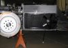
The most significant move is the radiator. I moved that radiator to just behind the passenger. I expect very little air flow back there, so I enlisted the help of a expert with lots of experience building cooling systems for rock crawlers. Rock crawlers use lots of horsepower to scramble up impossible mountain faces, but they do it at a very slow speed (i.e. no ram air flow). Due to the low ram air flow in the rear, the radiator is considerably larger than the RCR unit. Its a high tech piece with a 2 pass layout, 3 row core, and narrow passageways to maximize cooling. We then added the most powerful fans that SPAL makes. Due to the confined space, there is 1 pusher and 1 puller fan. It all fits within the SLC body with just a fraction of an inch on several sides.
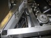
I've also mocked up the radiator hose, heater hoses, steam lines and a custom expansion tank.
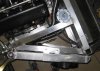
You may remember quite a while back I decided to mount the fuel tank as far forward as possible. The reason was that the radiator fits flush to the frame, so there is no room to route the heater/AC lines forward to the cabin. Moving the fuel tank forward allows just enough room to route the hoses between the tank and the vertical chassis member.
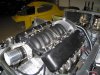
The custom expansion tank is meant to flow with the lines on the intake manifold, and clean up the firewall. It also hides the steam line coming from the motor as well as the pulley system. The fill neck is a bit hard to get to, so it may not make it to the finished car.